Last week I purchased a Zifon YT-1000 Motorised Pan Tilt head for about AU$90. It had advertised remote control over 2.4 GHz, but I wanted to see if I could hardware hack it to allow remote control over a WiFi network!
For those who don’t know, a pan tilt head is a type of camera mount that allows specific control over a camera’s pan or tilt without affecting the other axes of rotation. This allows for smooth camera movements, crucial for video! A motorised pan tilt head uses motors to electronically adjust the rotation axes (often remotely!)
And no, not every camera movement is called a pan...

You may have heard of PTZ Cameras before - these allow for control over its Pan and Tilt, as well as its Zoom - however it’s unlikely that you’ll see a “PTZ head” because it’s impractical to universally control the zoom for every type of camera system.
Zifon YT-1000
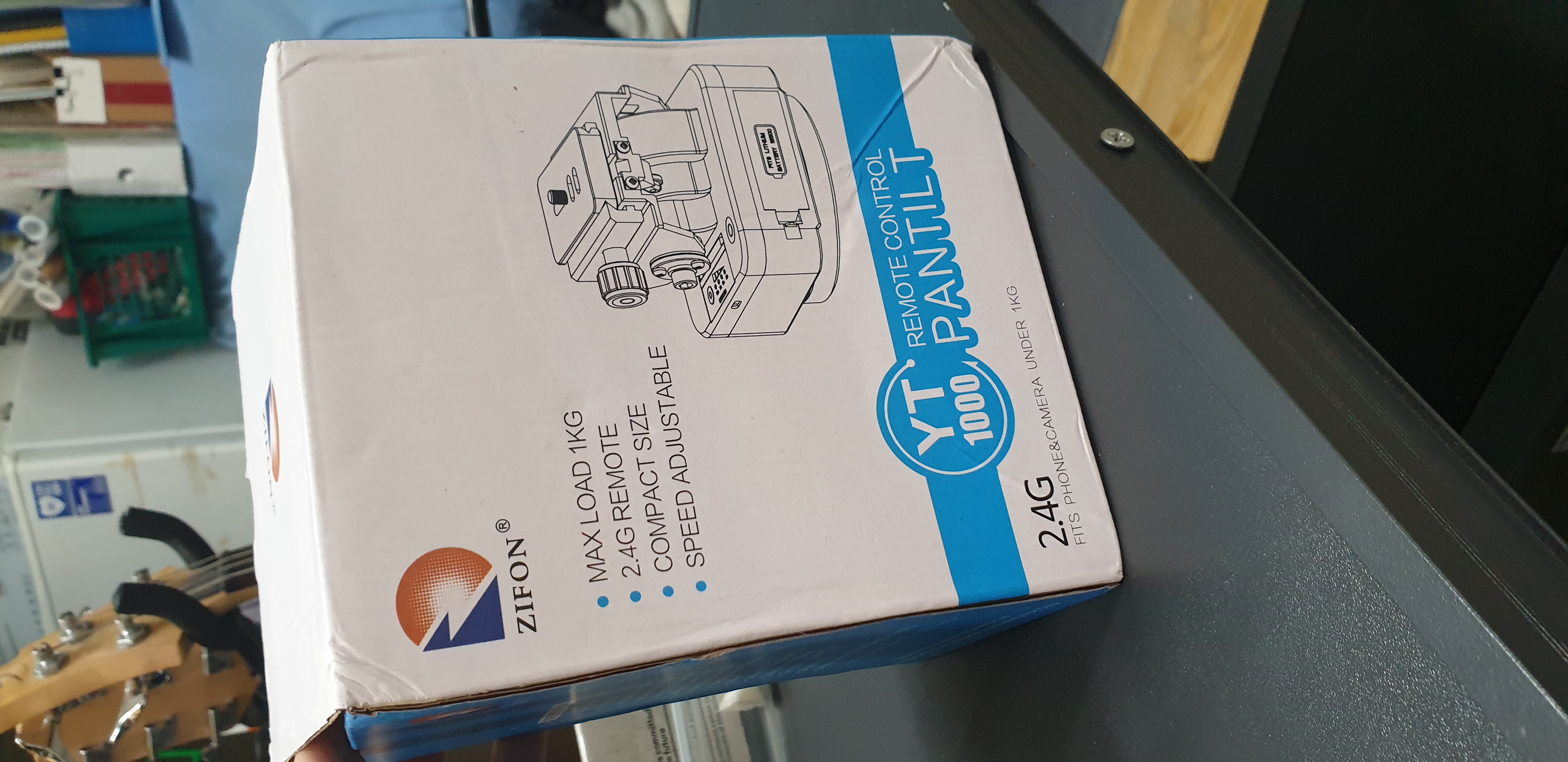
Features
- “Max” Payload: 1 kg*
- Charging: USB-C
- Remote Control: 2.4 GHz
- Simultaneous X and Y axis: No
Payload Limitation
Despite the product being advertised as supporting a maximum load of 1 kilogram, I was pleasantly surprised to see it operate quite well with a 2.2kg payload! I tested my EOS R with a 70-200mm, and the unit operated quite happily and smoothly even at the maximum tilt angles.
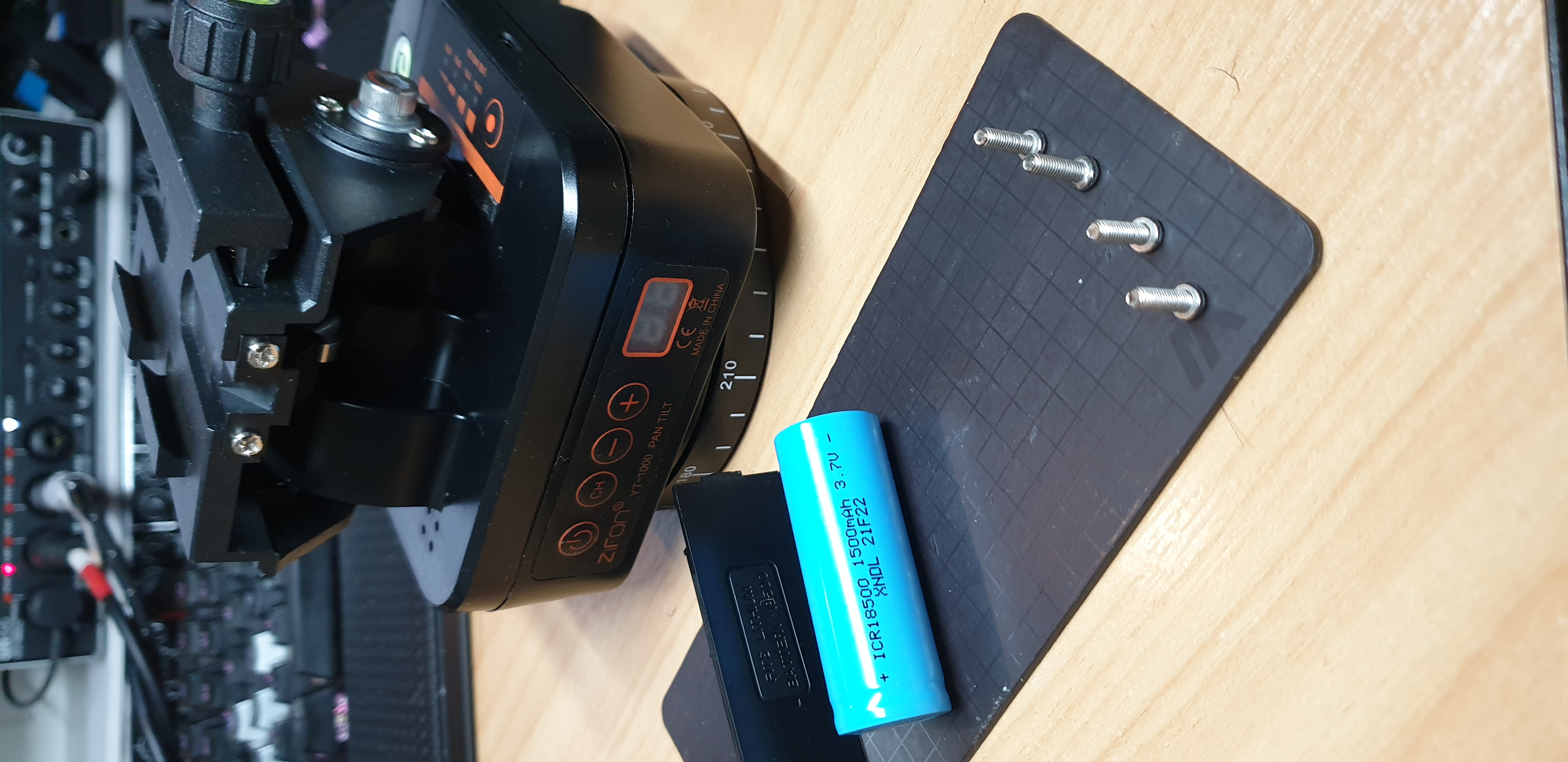
What’s In The Box
- Pan Tilt Unit + 18650 (3.7V) battery
- 2.4 GHz Remote + 2x AAA Battery
- USB-A to USB-C charging cable
- Quick Release Plate (Arca-Swiss compatible)
- Phone Mount
From the looks of it, I was unable to control both the pan and the tilt simultaneously with the remote; something I was thinking of implementing with my hardware hack. The idea was to use an ESP8266 microcontroller, which had an inbuilt WiFi chip.
So what was the plan?
- Take a look at the circuitry
- Find supply voltage points
- Find control signal points
- Analyse control signals
- Replicate control signals
- $$$
What’s In The Box
You see all of these “unboxing” videos, but is it really an unboxing video unless you take absolutely everything apart????
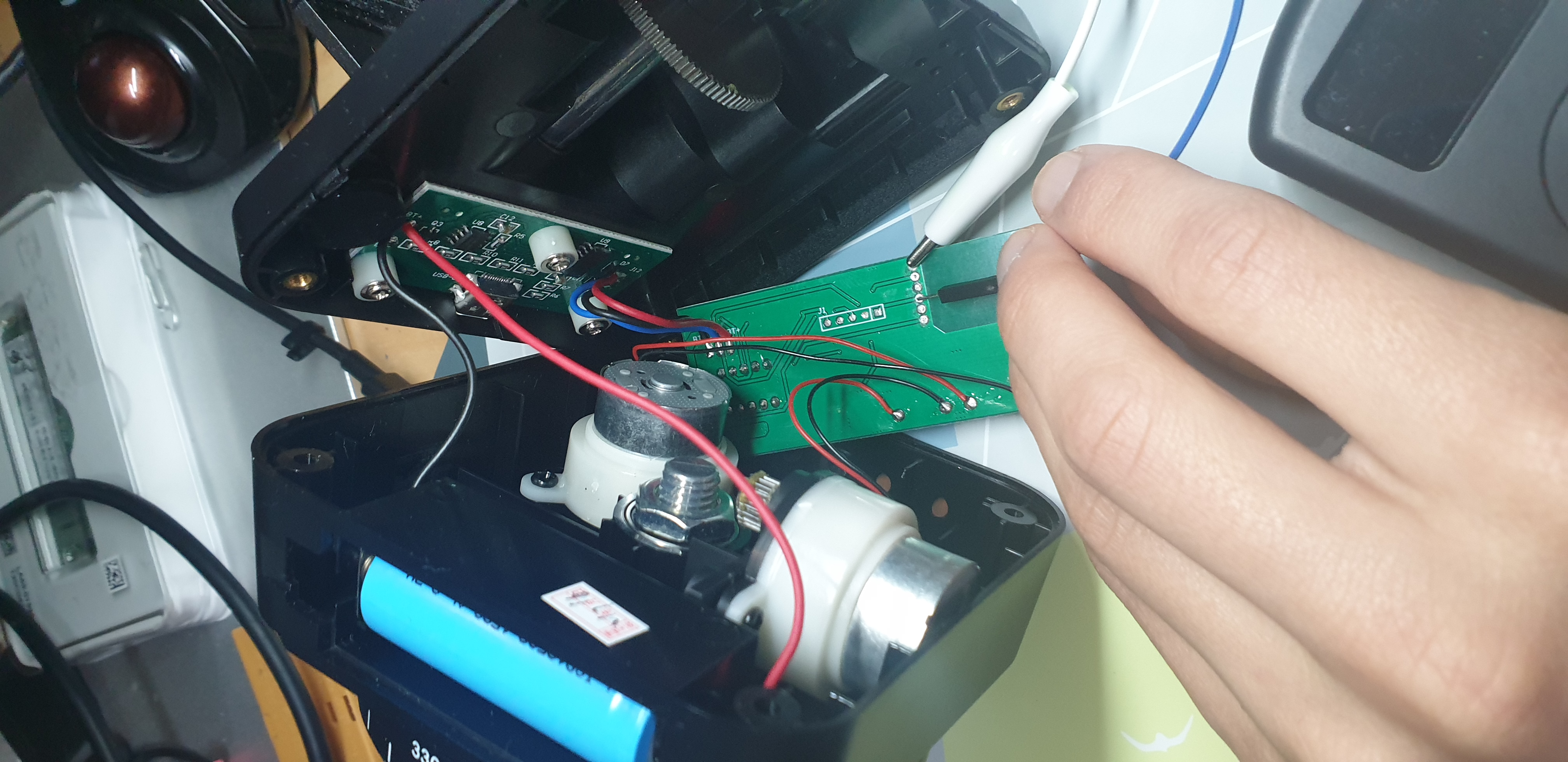
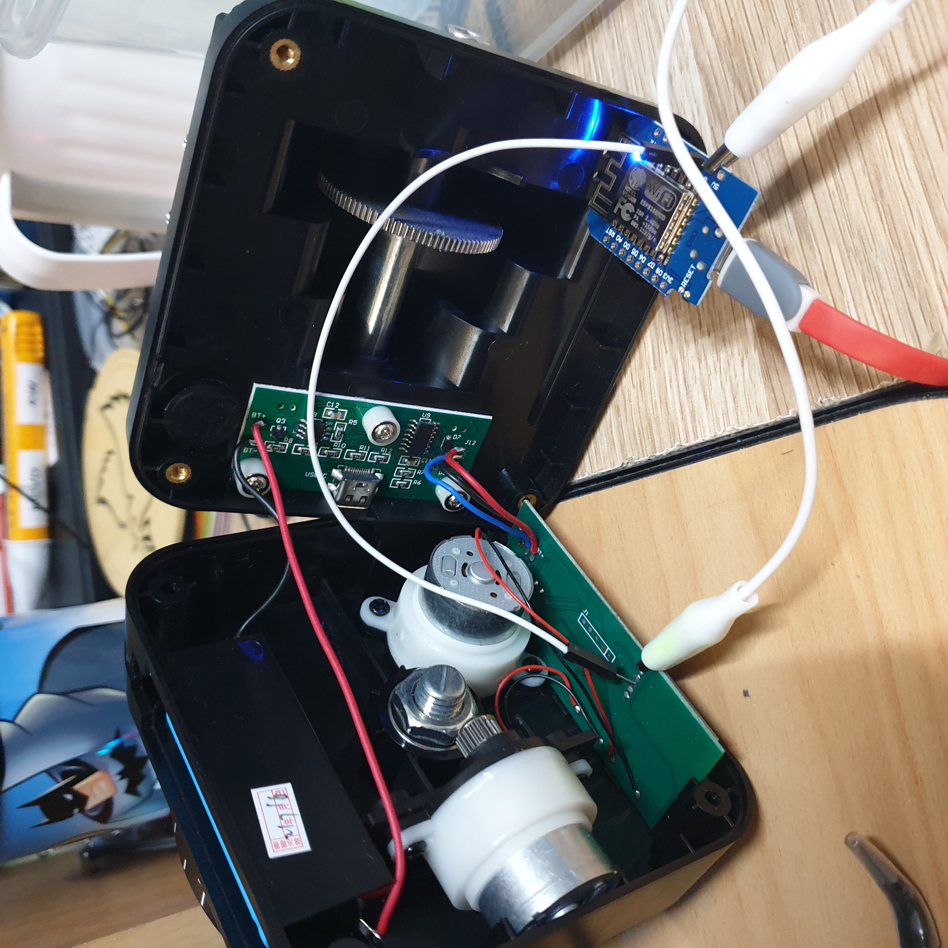
Okay let’s open it up!
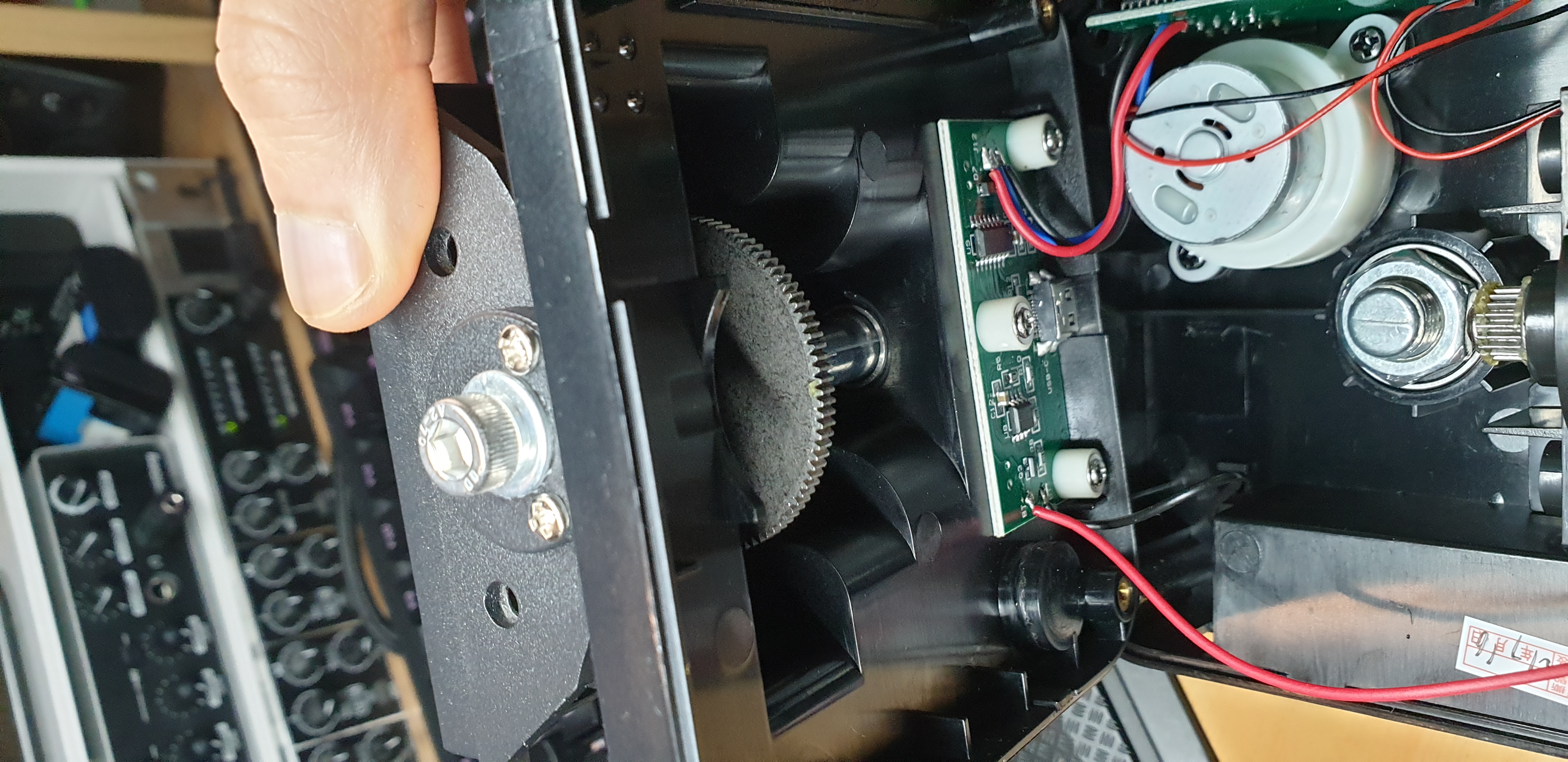
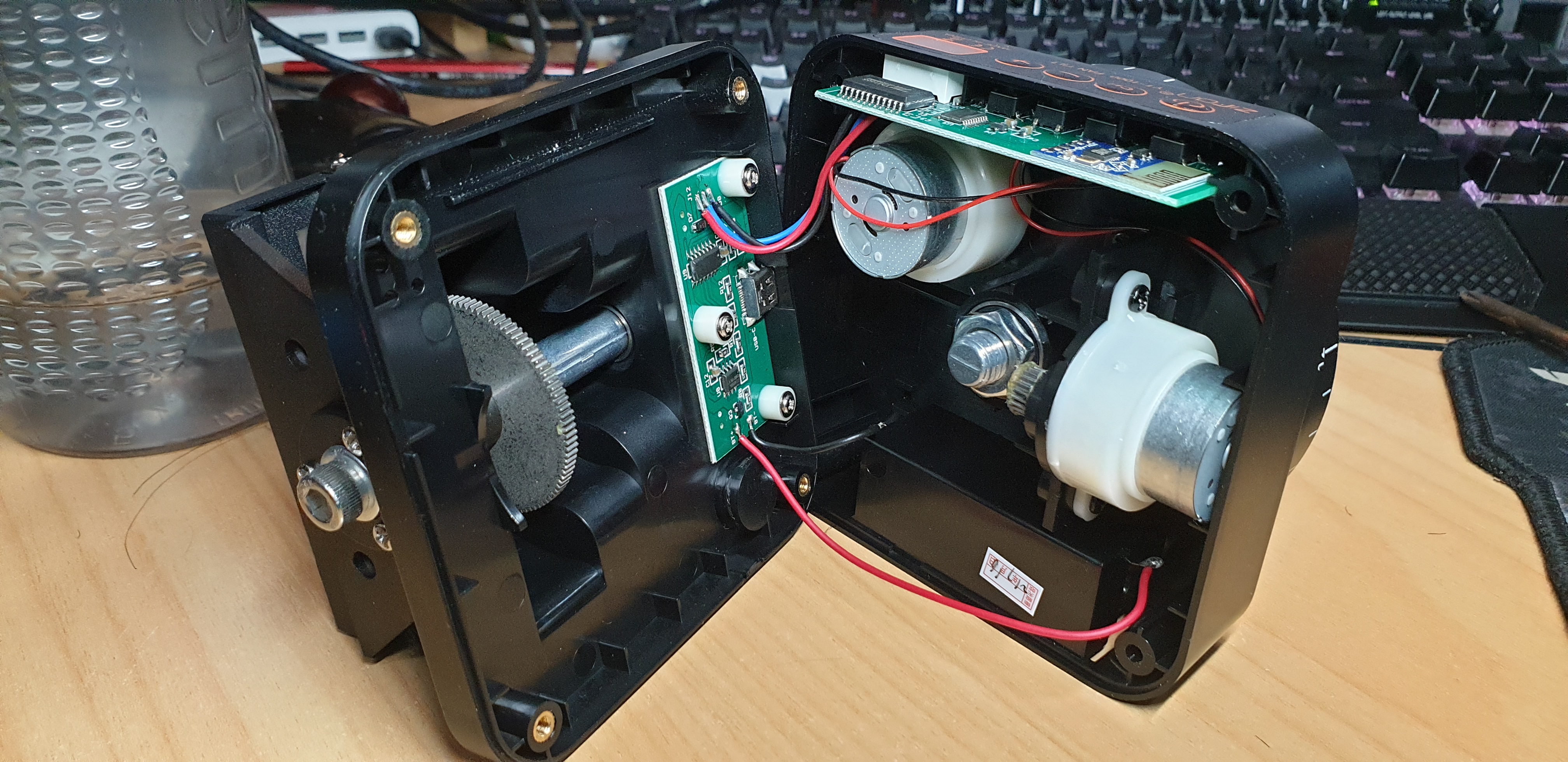
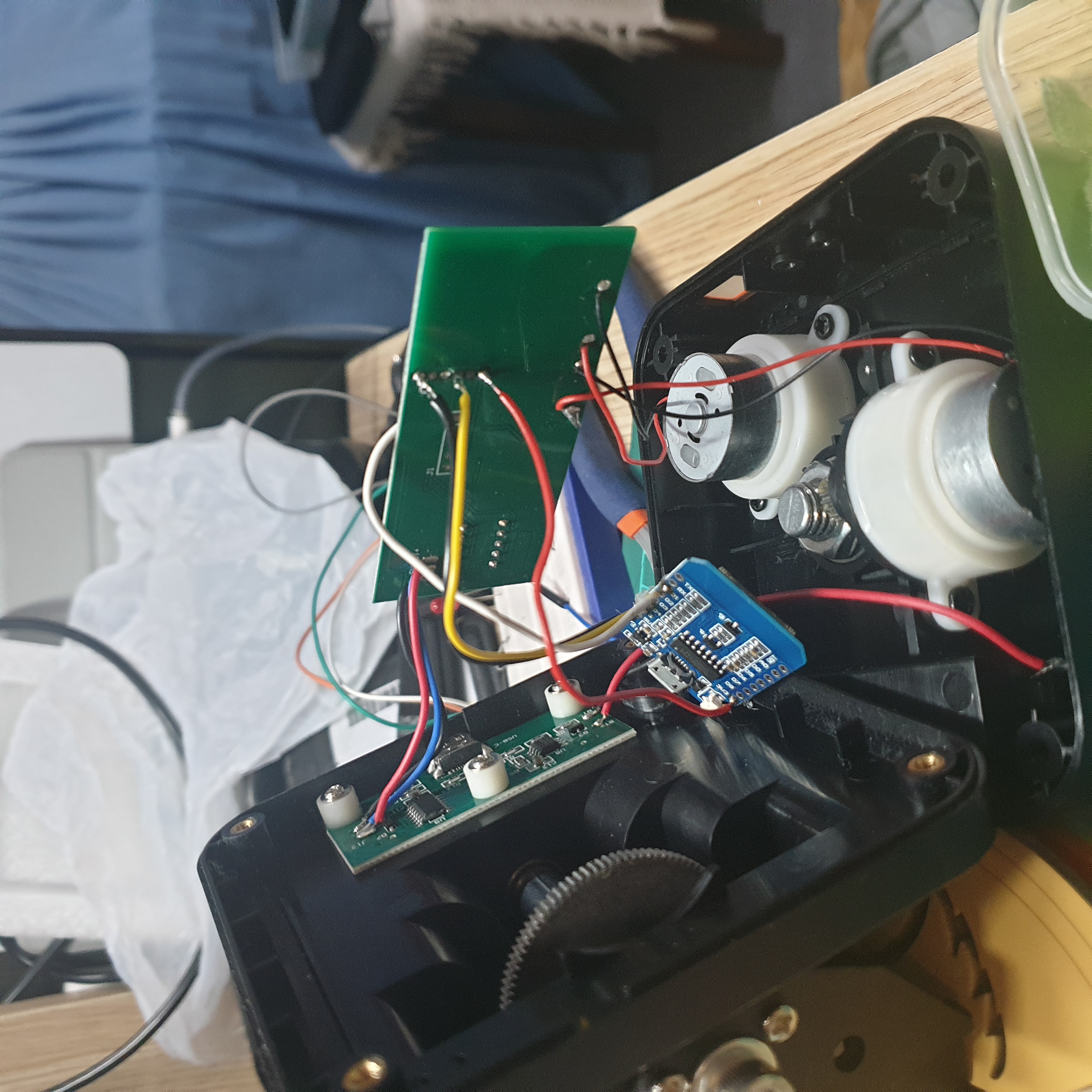
Inside we see two circuit boards and two motors that provide geared torque. The wires were pretty short, and I had actually accidentally yanked free a few of them whilst performing this hardware hack!
Main PCB
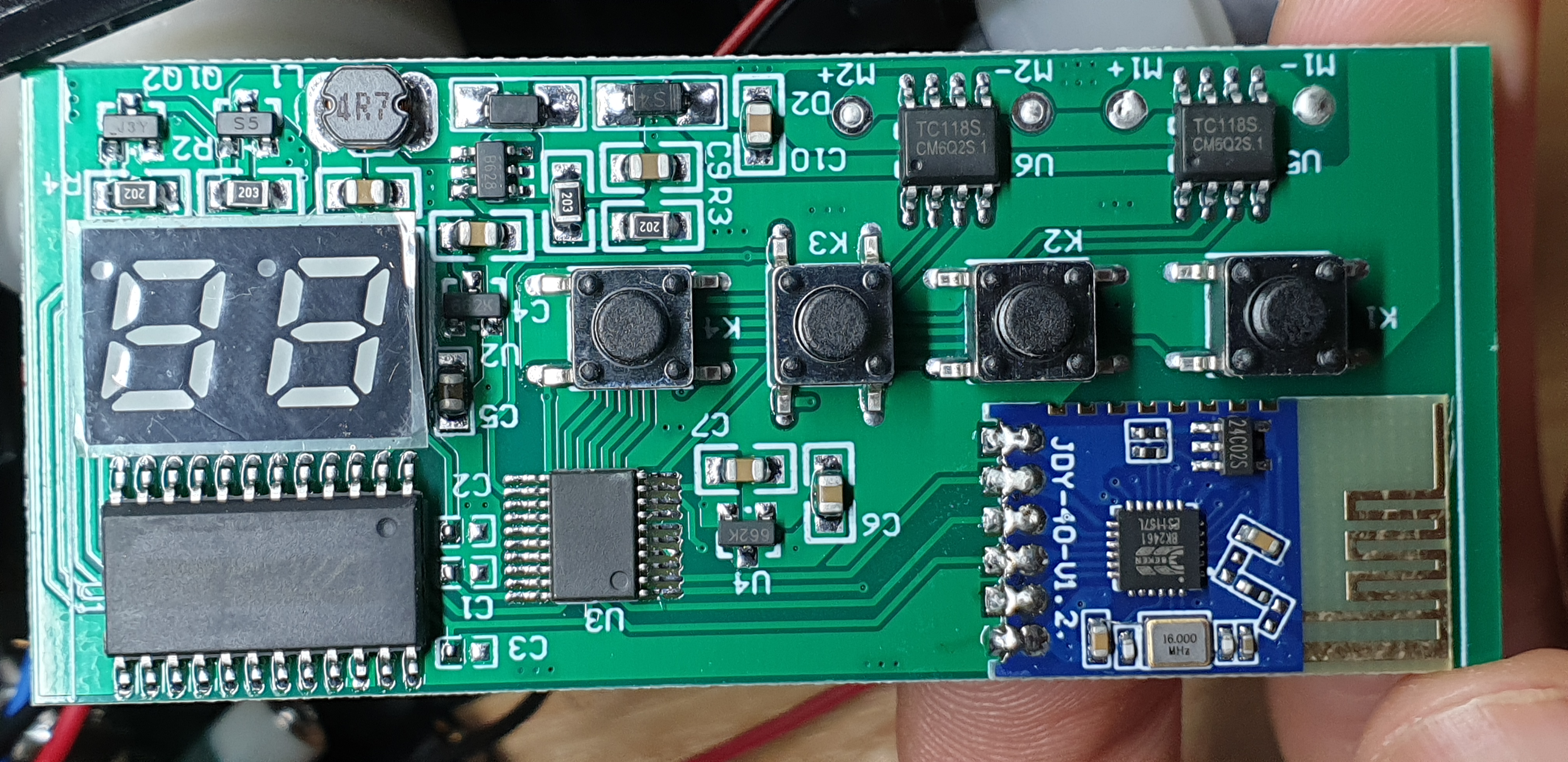
On the main PCB we see the bulk of the functional circuit. A bunch of ICs, some push buttons for the power and channel select settings, two 7-segement displays, and a bunch of resistors and power regulators (eh).
Let’s have a look at the ICs!
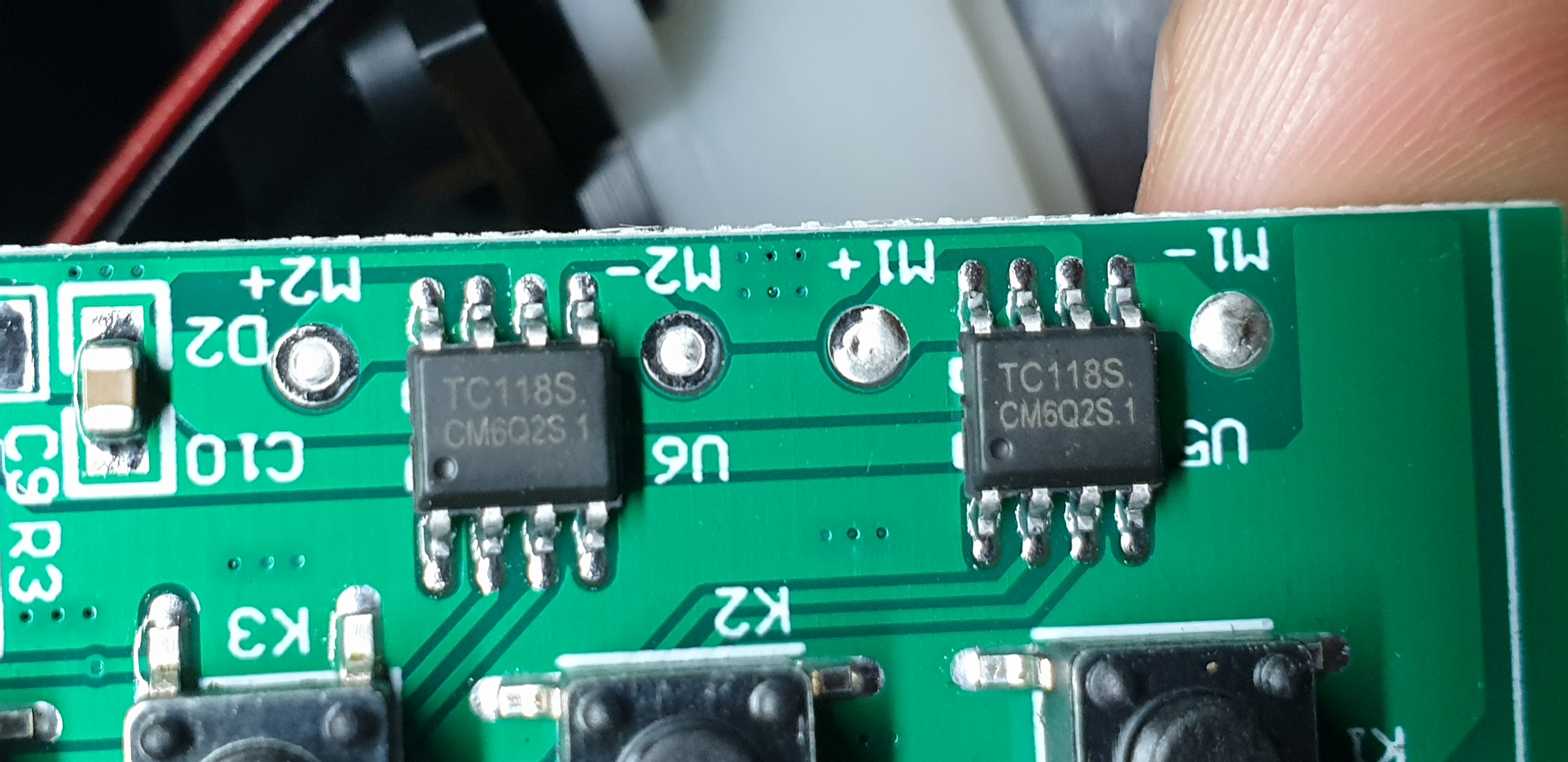
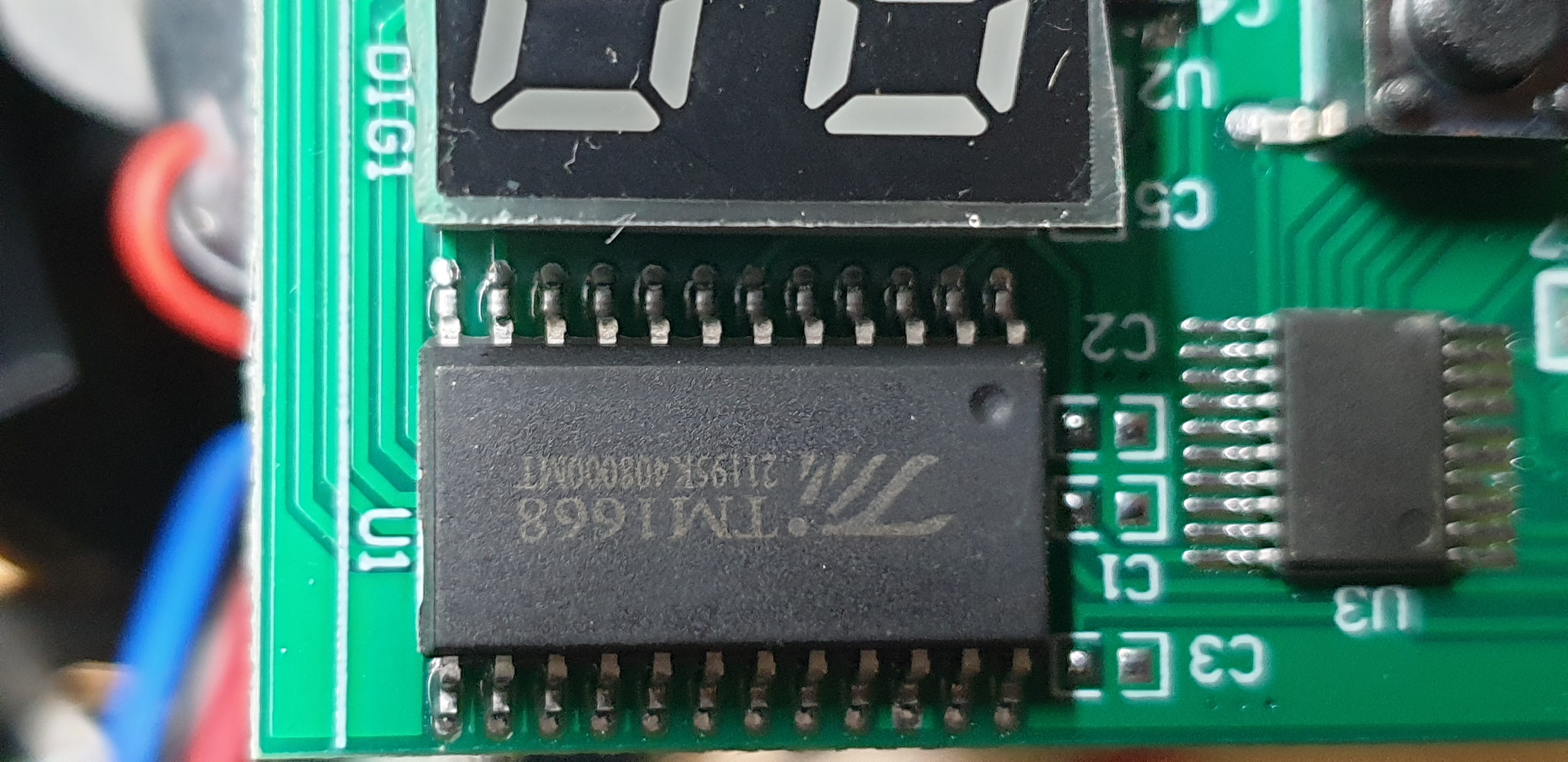
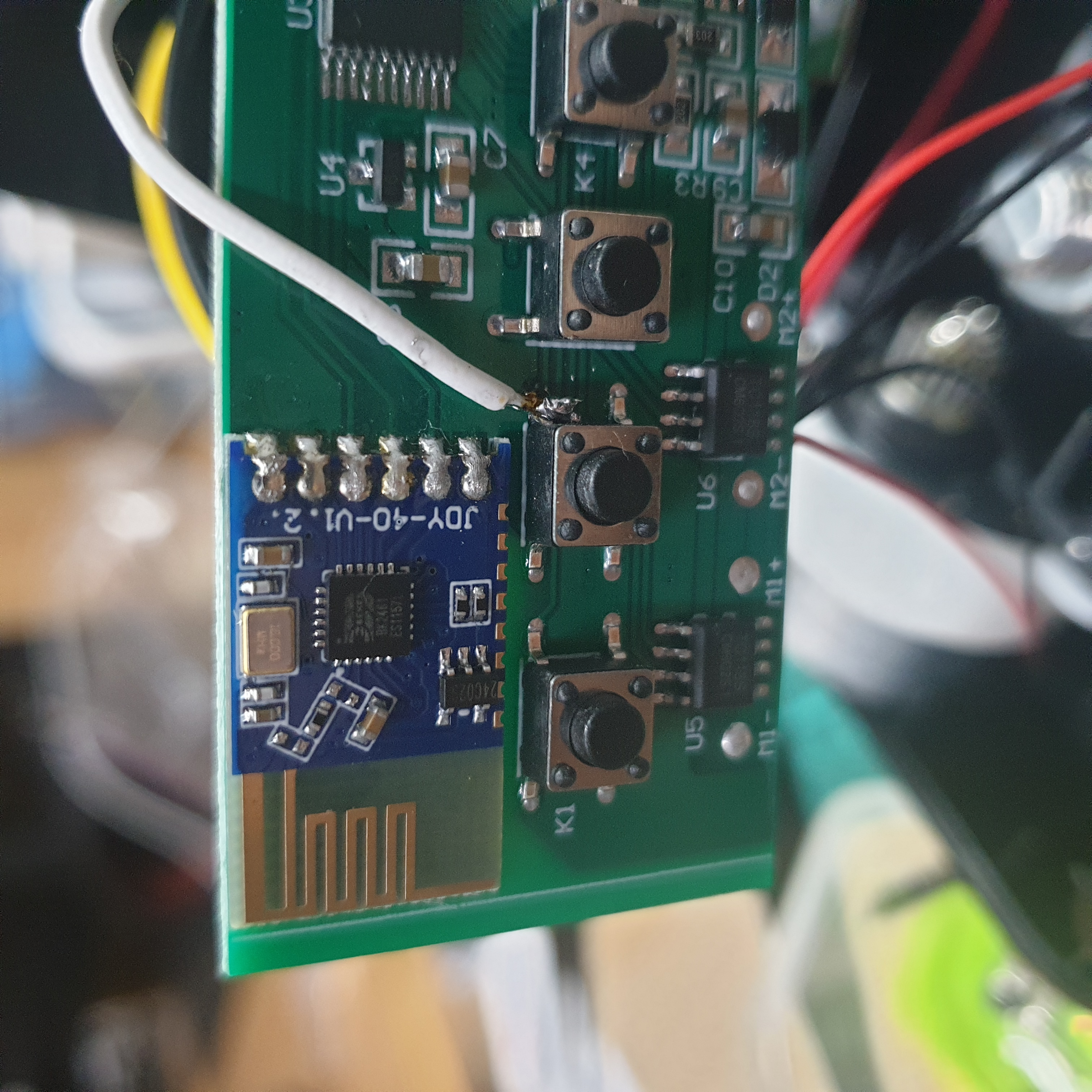
JDY-40- wireless serial moduleTC118S- DC motor driver ICTM1668- LED display IC and keypad driver???
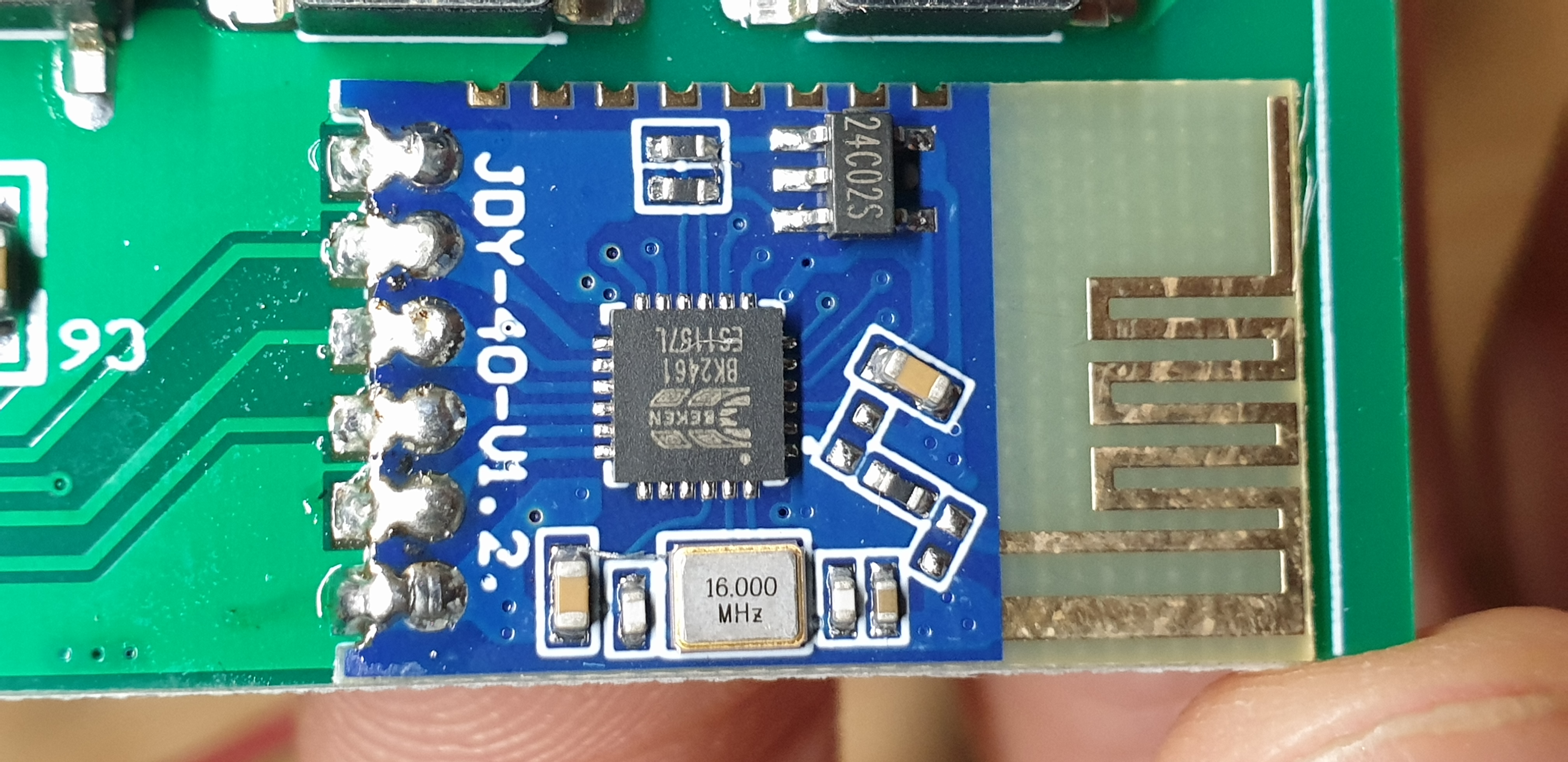
The most interesting ICs were the JDY-40 and obviously the IC with no markings on it.
I assume that the JDY-40 was the transceiver for the remote control, definitely an area on the board that I would want to check out later!
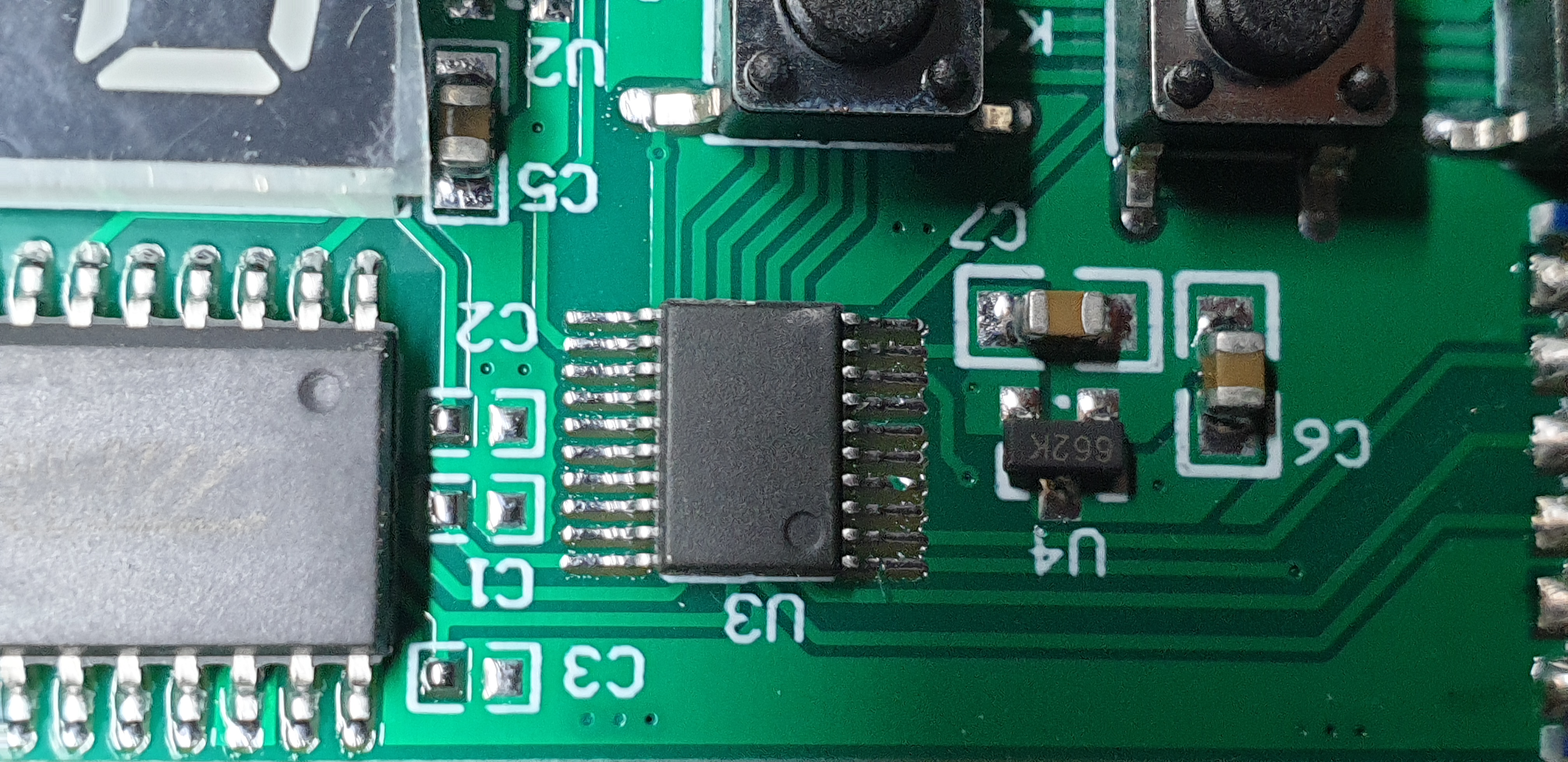
As for the blank 20-SOIC, this looked like the main control unit (MCU) for the device.
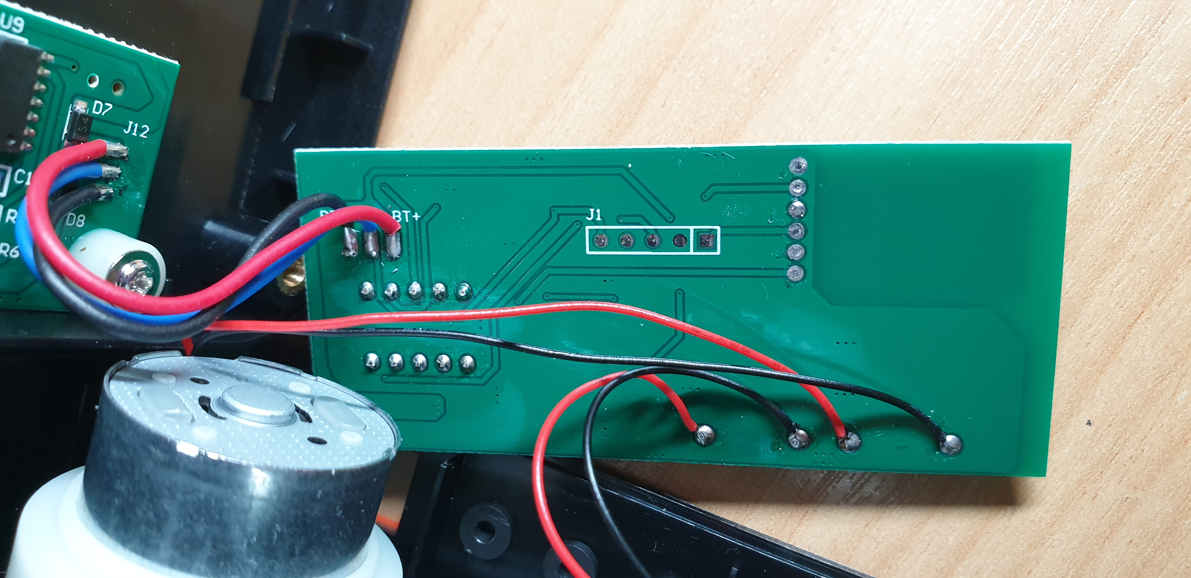
As for the back of that PCB, we can see a few exposed contacts at, and to the right of J1.
Power PCB
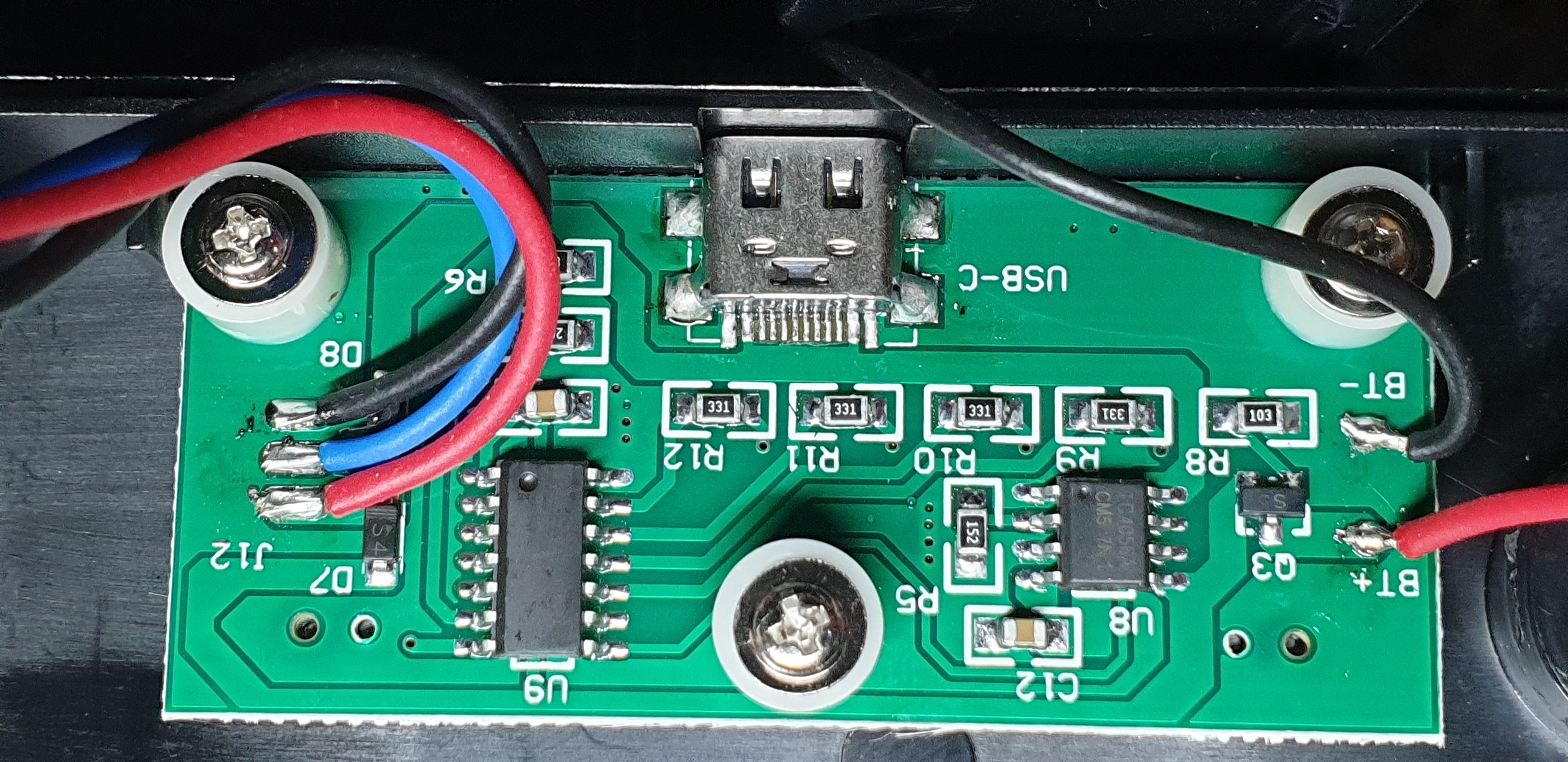
This PCB was responsible for the power operations of the circuit
- Charging of the battery
- Battery level indication
- Supply voltage to the main PCB
- Tilt motor supply voltage (blue lead)
I didn’t bother to unscrew this circuit, as it was likely just ancillary power-related stuff
I should also mention that on the top of the unit are two “stop switches” which cut off the power (blue lead) to the tilt motor if pressed - these stop the tilt operation when the maximum physical tilt angle has been reached.
Pinout
GitHub: featherbear/zifon-yt1000-wifi-acu/blob/master/research/parts.md
After having an inspection overall circuit components, I wanted to take a closer look at the layout - so I whipped out my multimeter and started to probe the circuit. You can find my results here
Resources
Whilst I had most of the pins, I wasn’t sure what a few of the pins on the MCU (U3) were for; namely J1.2 was connected to U3.9, and J1.3 was connected to U3.8. I think these might be some sort of flashing ports for the manufacturer to update the MCU (perhaps?).
Nevertheless I figured out enough information to move to the next stage
Serial
GitHub: featherbear/zifon-yt1000-wifi-acu/blob/master/research/serial-communications.md
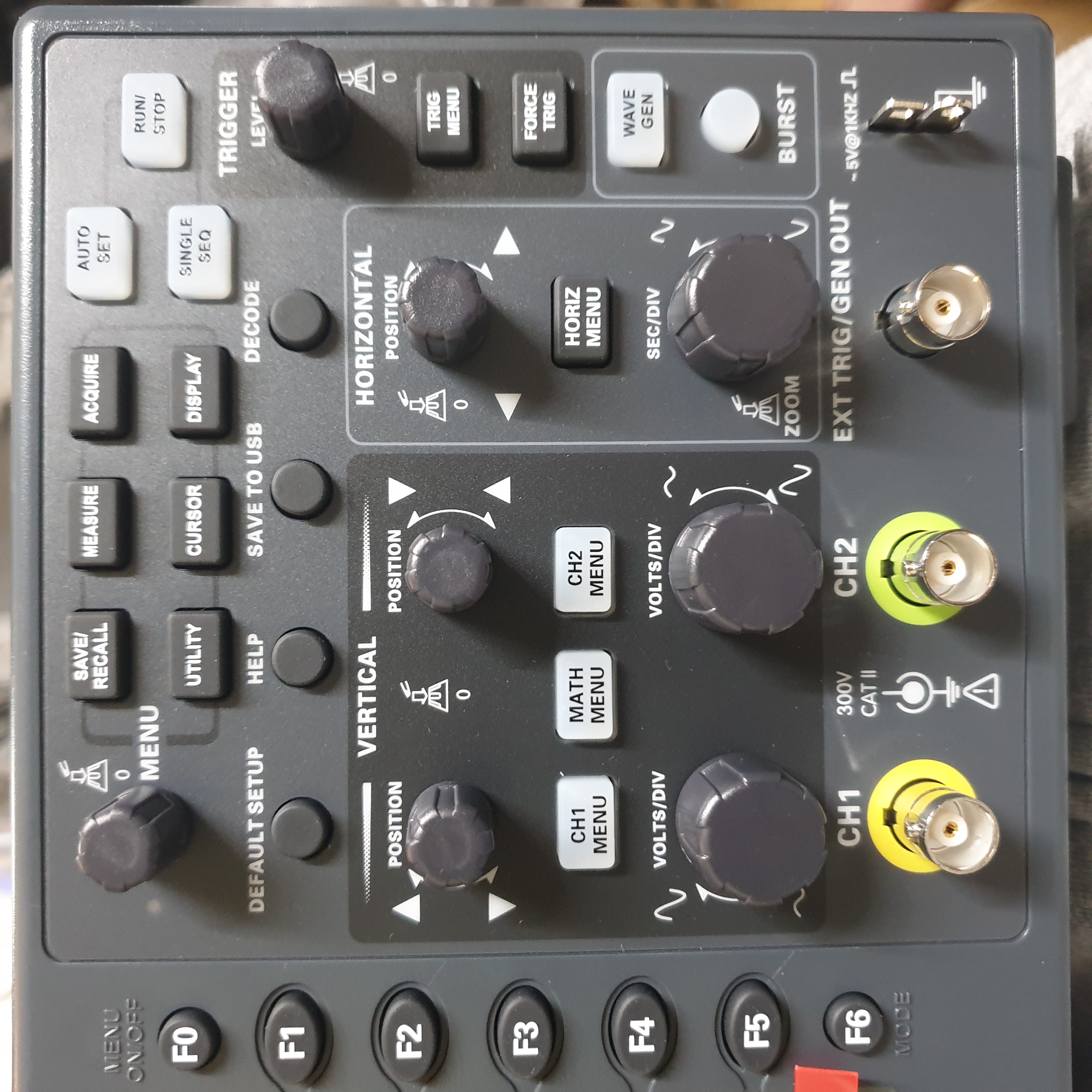
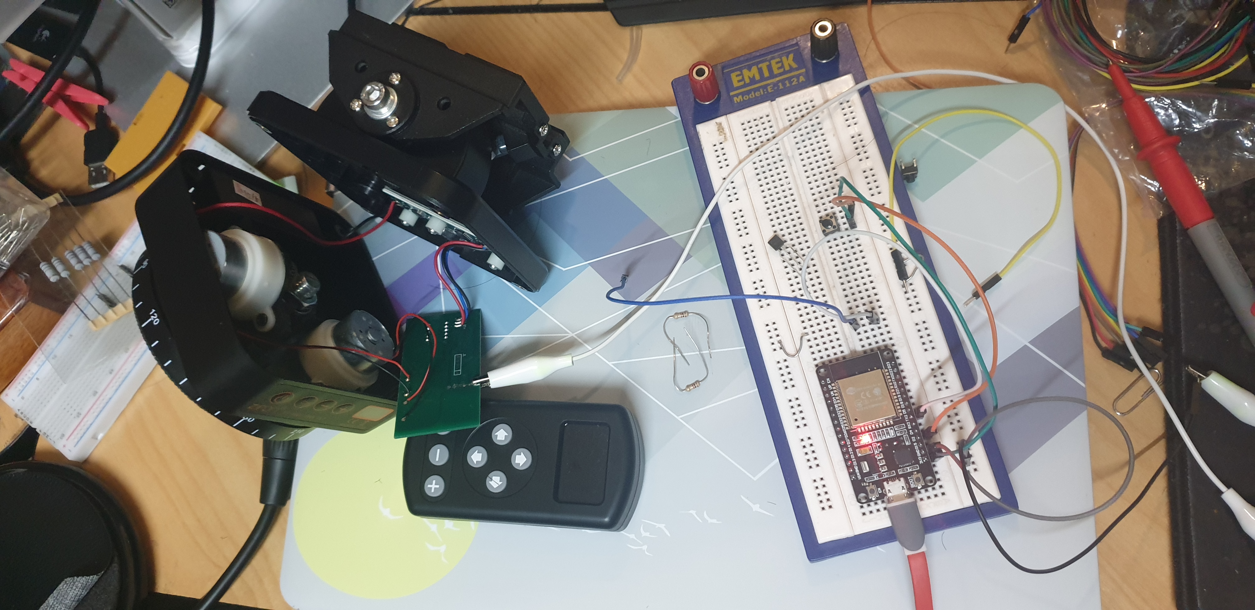
Now knowing that the MCU was (ultimately) controlled by serial commands, the next step was to reverse engineer the instructions. Unfortunately I didn’t have an oscilloscope (Update: I now do 😉), so I had choice of finding my USB to TTL Serial adapter, or writing some code for an Arduino I conveniently had next to me.
(I did the latter, simple code linked here)
First I had to figure out the baud rate. As I didn’t have an oscilloscope (at the time), I had to cycle through the different baud rates until I could see something intelligible; and also hopefully repeated (i.e. the same remote instruction being transmitted again and again).
After a few attempts, I saw the bytes 53 54 41 52 54 0D 0A being transmitted by the MCU to the transceiver at 9600 baud. First noticeably to me were the 0D 0A bytes, which translated to \r\n, the carriage return and new line characters. The other preceding bytes were also intelligible, representing the string START.
(To be honest I probably could have guessed 9600 baud, which was the default baud rate for a majority of devices, let alone this serial module)
When holding down the motor button(s) on the remote, I was able to see the data being sent repeatedly from the transceiver to the MCU. Luckily all of the instructions seemed to follow the same pattern, a series of 3-byte packets where an instruction byte was padded between a channel byte on each side (see here)
Rinse and Repeat
GitHub: featherbear/zifon-yt1000-wifi-acu/blob/master/research/serial-listener/src/test_send.cpp
After having successfully RE’d the protocol, I programmed the Arduino to send bytes instead of receive.
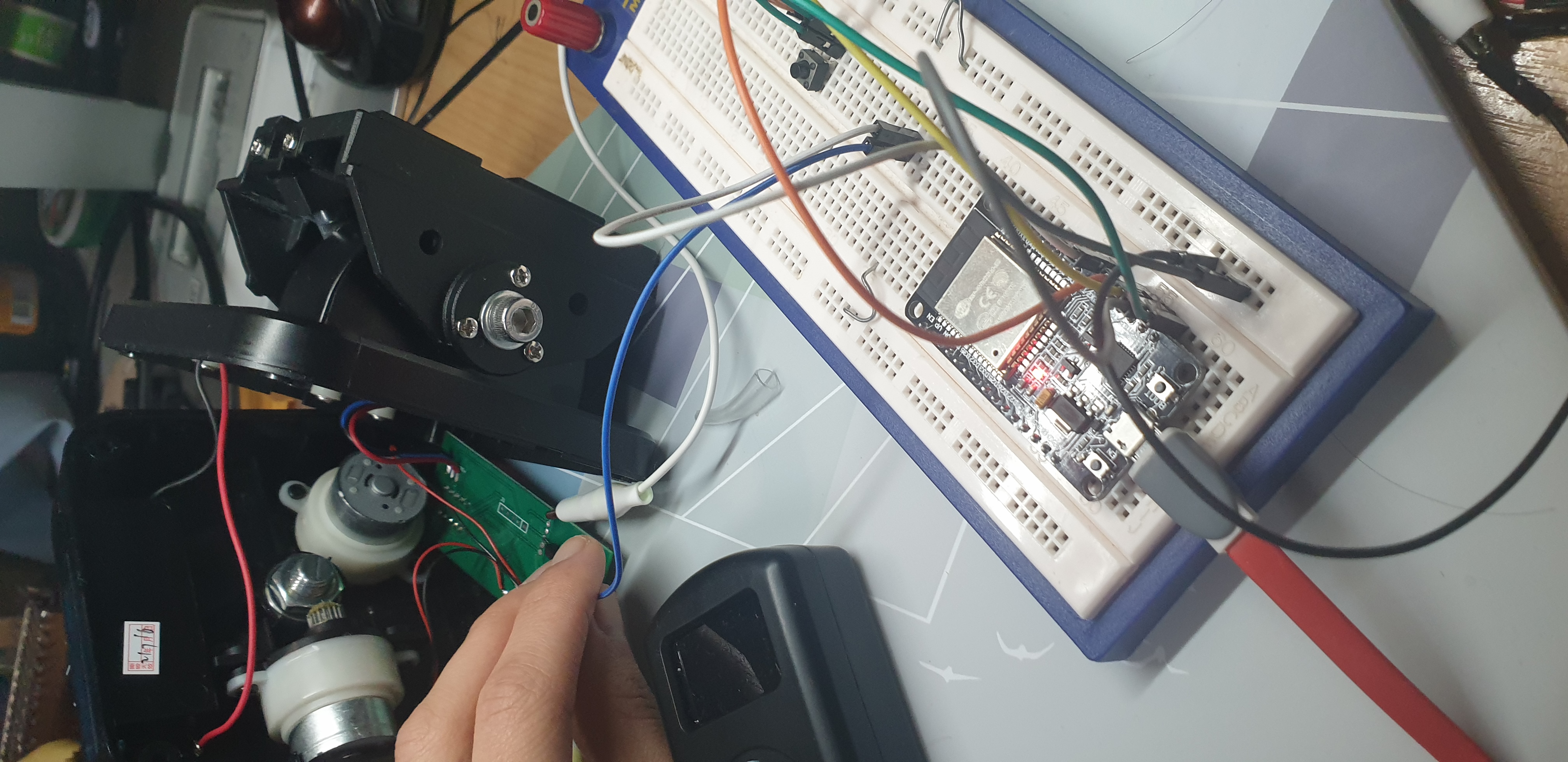
Upon trying to send both pan and tilt instructions in alternate succession, I didn’t get quite the amazing result that I wanted… Whilst the pan motor seemed to be operating “okay”, the tilt motor wasn’t generating enough torque. I suspect that this is due to the time required for motor spin-up; If I don’t supply power for a sufficient duration, the motor won’t be able to speed up to a “PWM-able” speed.
I tried changing the pan:tilt packet ratio, but it didn’t really help that much..
I wonder if the device is not able to do simultaneous axes instructions because the circuit wouldn’t be able to provide enough power to spin both motors together, and as such the MCU was designed to only operate one motor at a time..
I also found out that I was no longer able to use original remote controller whilst my Arduino was attached to the circuit 😭. It turns out that when serial communication is idle, the output state is HIGH - and that’s an issue as the JDY-40 would not be able to send its own pulses :(
Some ideas I had in mind were to stop the Arduino’s serial communication and start it back up when needed (using Serial.end() and Serial.begin()) however this seemed to be time-expensive. I also considered trying some hardware approaches such as using some sort of NPN transistor / gate… but I didn’t get very far. Eventually I started to consider other plans such as putting the Arduino inline between the JDY-40 and the MCU… but that would be a big hassle as I would have to desolder the serial module to make it no longer parallel to the circuit.
However! After more research I was reminded to the fact the Arduino (well at least my ESP32 and ESP8266 chips) had internal pullup resistors! This meant that when I wasn’t wanting to transmit any serial data from the Arduino, the pullup resistor would effectively open-circuit the Arduino from the MCU and serial module. Phew!
With dual control (not to be confused with simultaneous control) and instruction transmission working, I was ready to start putting everything together 🔥
WiFi ACU
There were three stages to making this auxiliary control unit.
Firstly I needed to write the hardware functionality to transmit the serial commands, as well as to (dis)engage the TX pin’s internal pullup resistor to allow the JDY-40 to operate when WiFi control is idle.
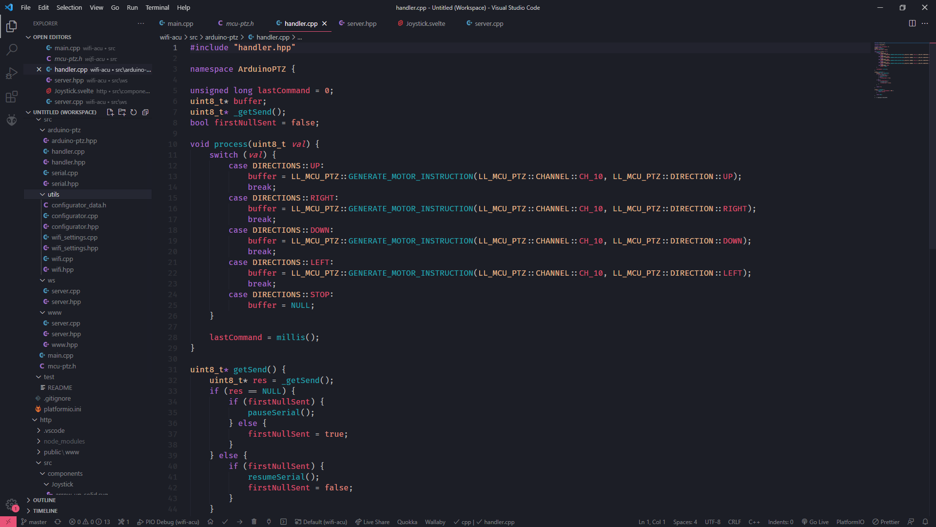
Click, clack, take a nap. Wake at ten and finish it then 🎵
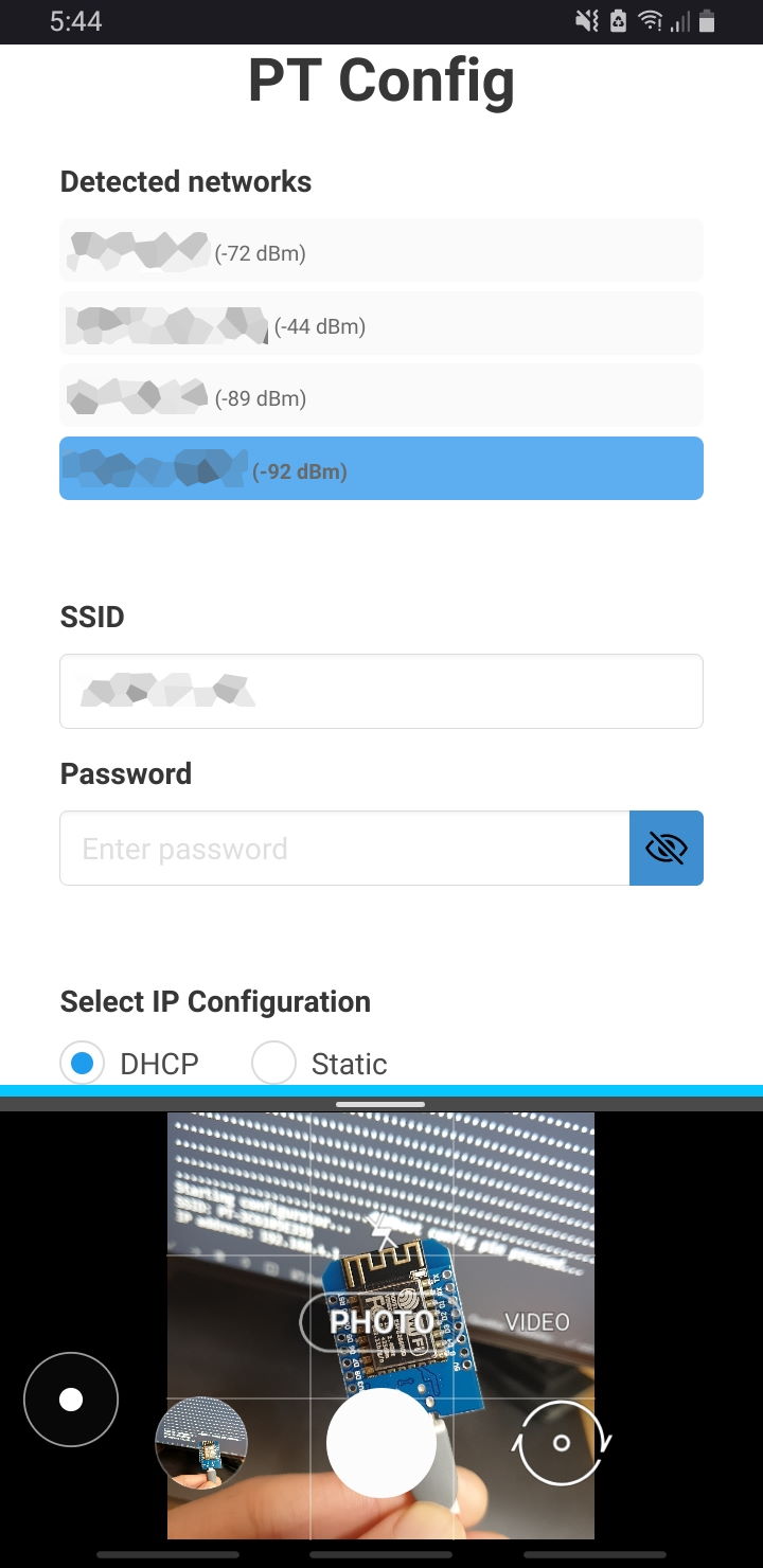
After the serial functionality was fine, I needed to implement wireless communications from the ESP8266 to a wireless network. I saved heaps of time by repurposing the WiFi configurator and web server code from my Talyte tally light project. Like with Talyte, the page is built with Svelte (my UI framework of choice), however taking lessons from last time I did not use Sapper - which made fitting all of the build files into the SPIFFS / LittleFS file system much easier (these file systems only allow file paths of up to 31 bytes long).
A note on wireless settings - I currently have the SSID / password / DHCP / Static IP configuration stored in separate files on the filesystem, as the ESP8266 doesn’t have an EEPROM (the ESP32 does) nevermind it does, but I wasn’t able to directly use the NVS.h library out of the box, so I just stored configs to the filesystem instead.
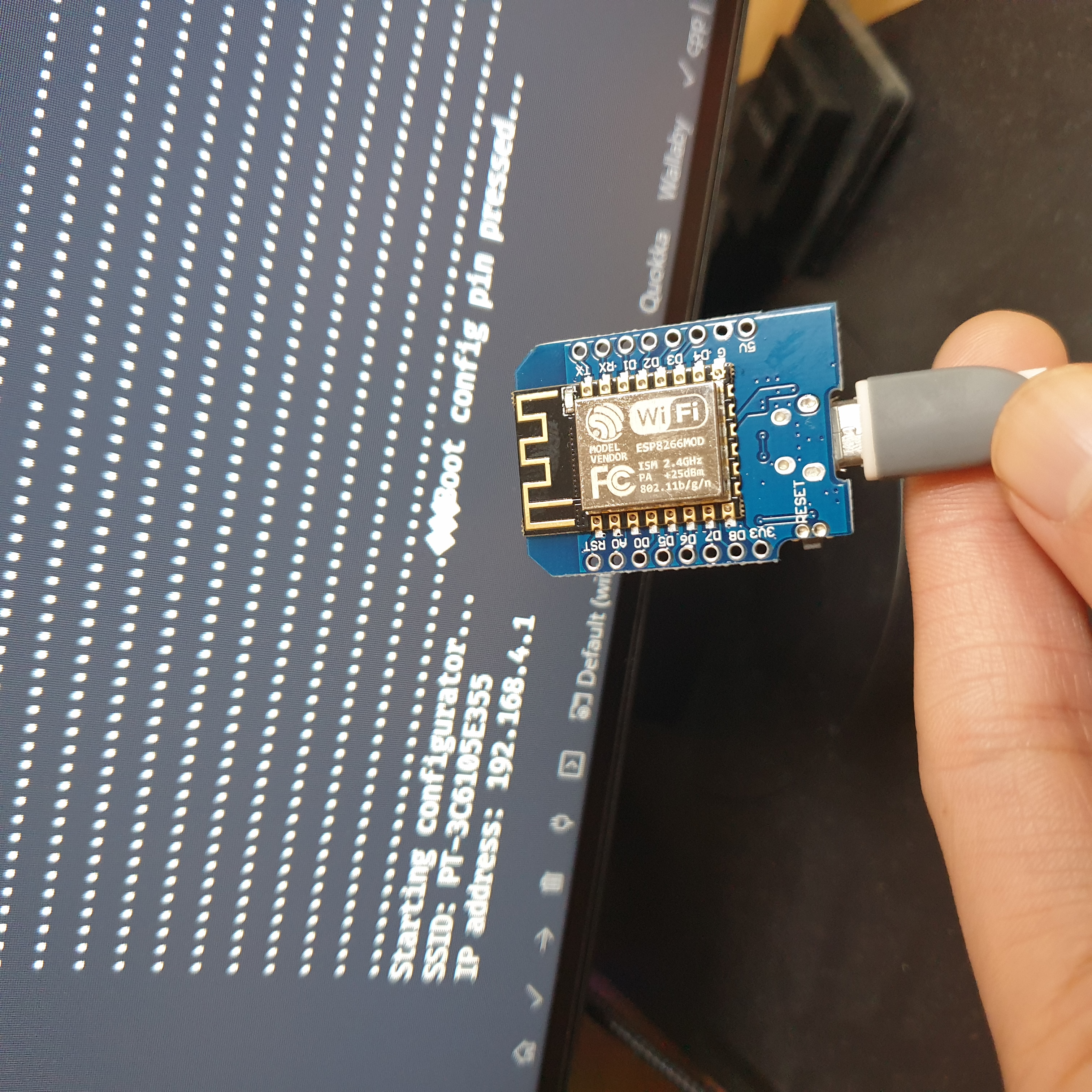
I also wrote some functionality to check if a pin was held down during boot, and if so the Arduino would go into WiFi configuration mode. I planned to connect this pin to the channel select button on the unit so I could change the wireless network easily.
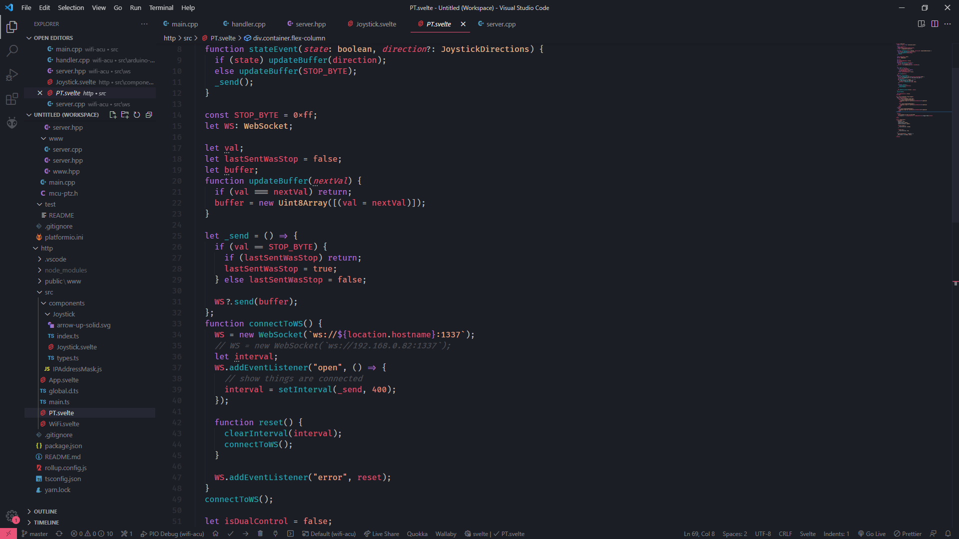
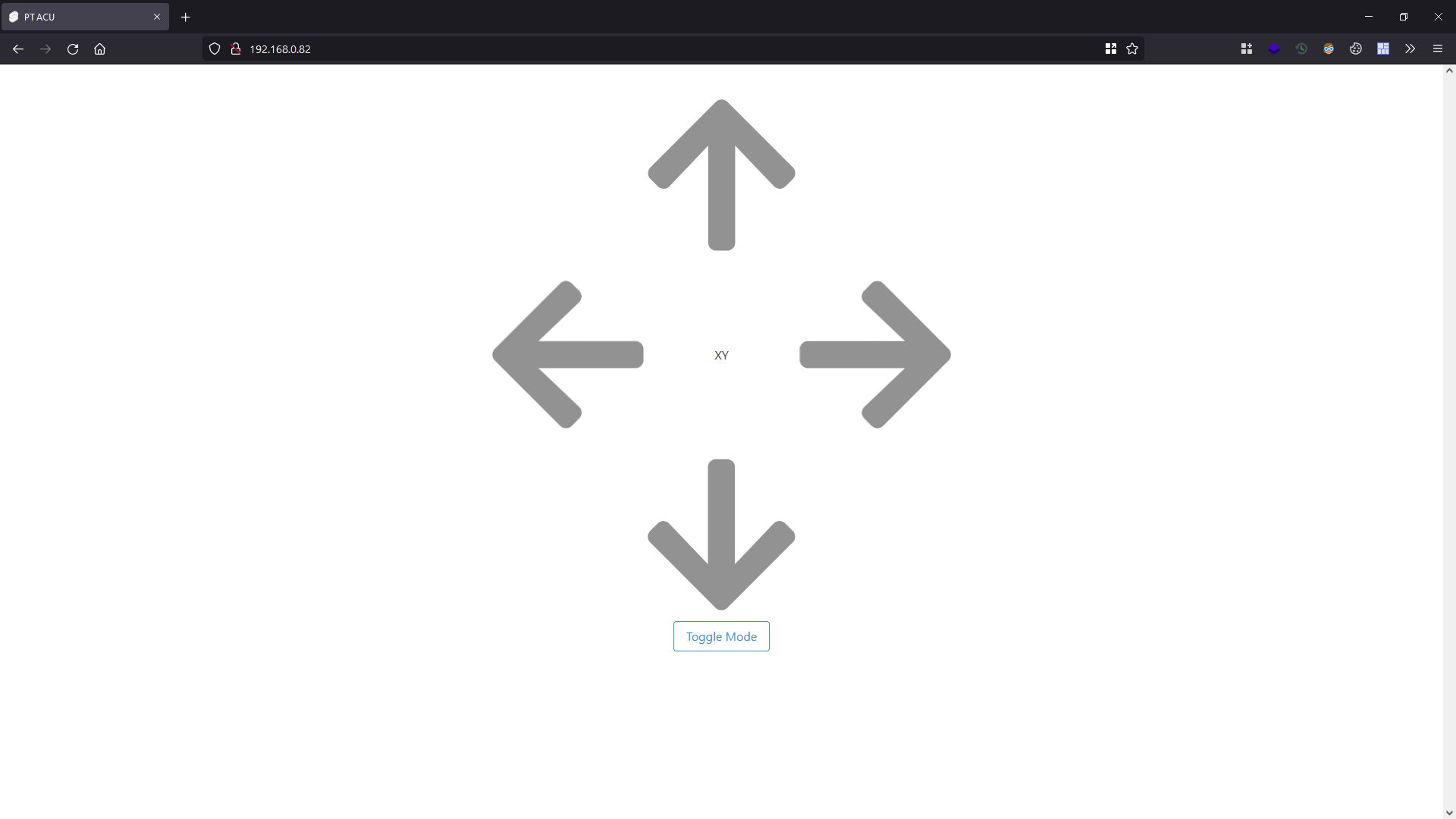
And finally, the frontend to control the device.
I created a simple directional pad (which is also W A S D and UP DOWN LEFT RIGHT compatible) that sends WebSockets packets to the Arduino.
I also implemented a direction queue, such that if you held a new direction whilst still moving in another, when you release the key for the new direction, the PT head would resume rotating on the original axis.
Originally I had the webpage send an instruction every 25ms or so, however I believe that this was too noisy and processor intensive for the ESP8266 to handle; so I changed my implementation to instead send deltas (change events only i.e. initial key down and initial key up events), and and the occasional state status (every 400ms instead!).
In the event that wireless communication is interrupted, or my browser closes / tab focus changes / I’m a bad programmer - to protect against a missed key up / release event, I also implemented a timer on the Arduino to only continue operation if an instruction packet was received recently.
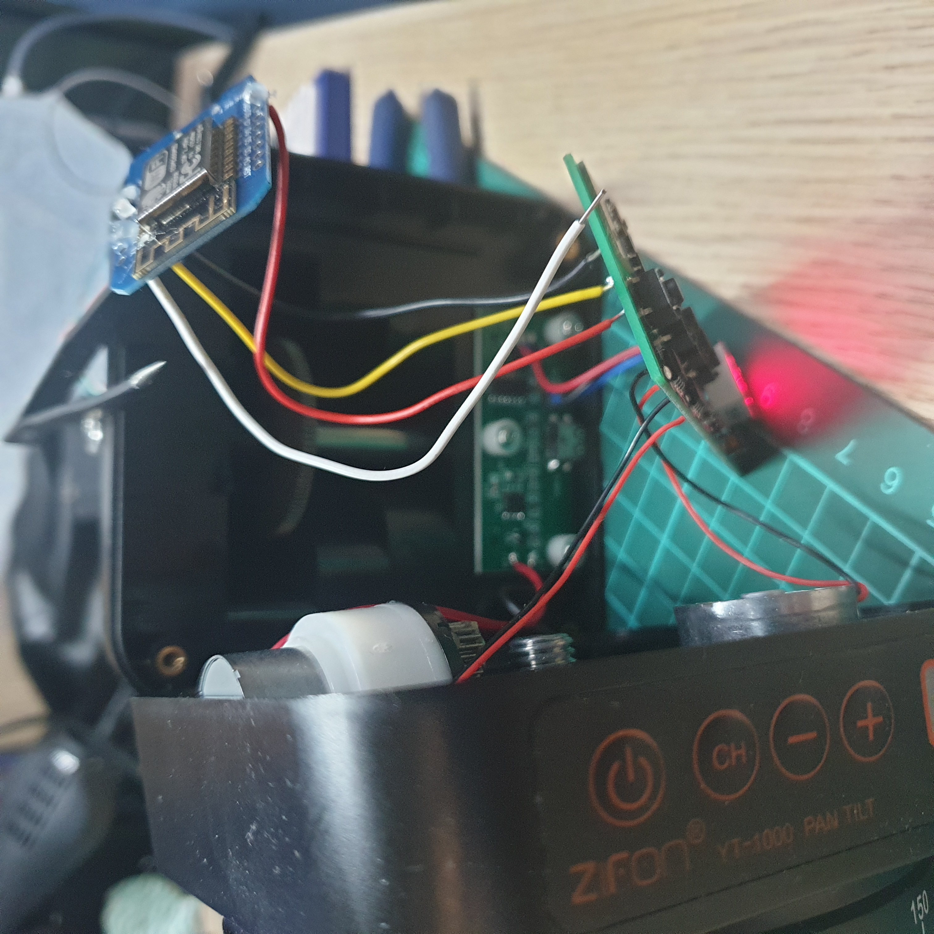
Integration
With everything seemingly working, I did a few more tests before I permanently soldered wires and closed up the case. As mentioned earlier, I had accidentally disconnected around 3 wires (at different times), due to the short cable lengths, so they had to be soldered back.
Dodgy Soldering ™
The tip of my soldering iron wasn’t conducting heat very well :( It made soldering pins quite hard as I had to protrude the tip and make contact with the side of the iron instead. (Update: Since, I have replaced the tip with a spare that I had lying around!)
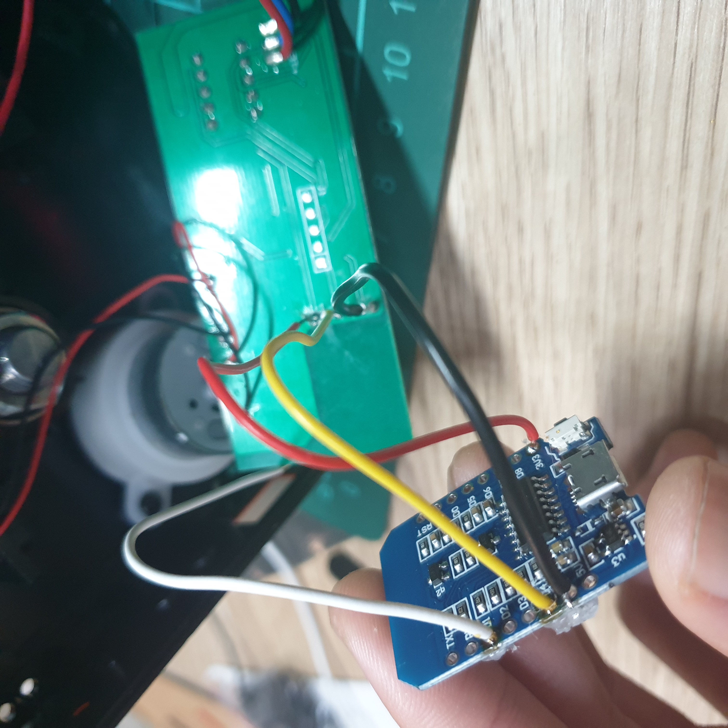
After everything was soldered, I proceeded to stuff the circuit board and all the wires into the case. I realised that the white wire (connected to the boot configuration mode pin) was interfering with the lid closing down, so had to break part of the plastic to get it to fit. If I ever do this mod again (which I might considering how well this worked!) I’ll remember to route the boot configuration mode wire a different way!
Alas, we’re done! And I’m actually really proud with how this turned out.
I haven’t really analysed the battery life detriment of connecting up the ESP8266 (I didn’t change any of its clock frequency settings) - but I also don’t really care as I have in mind to keep the unit connected to some power bank anyway
We out!
Update: 5th February 2022
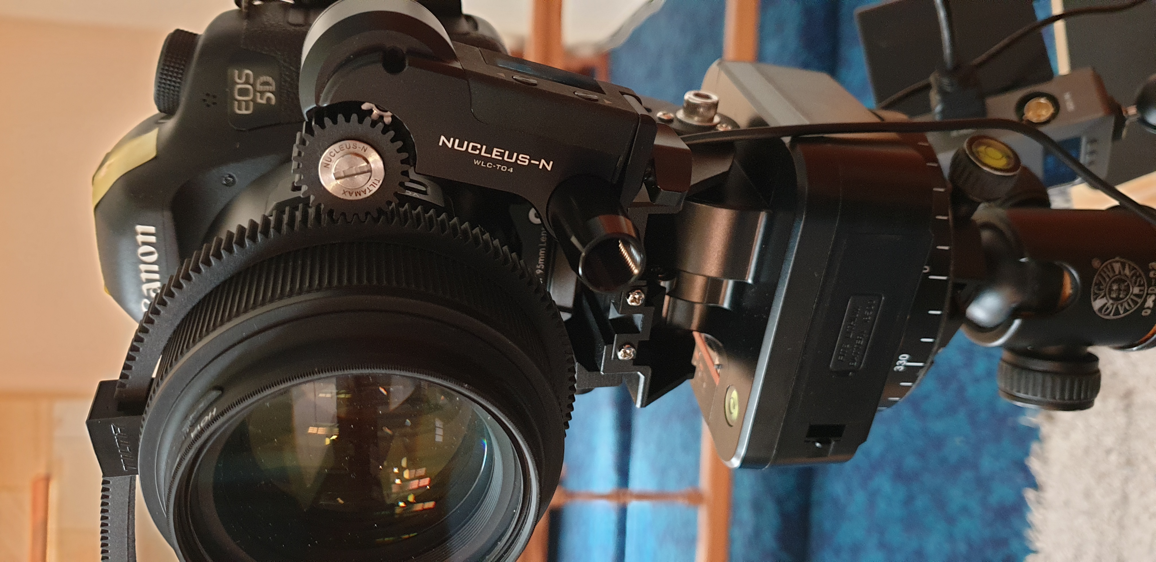
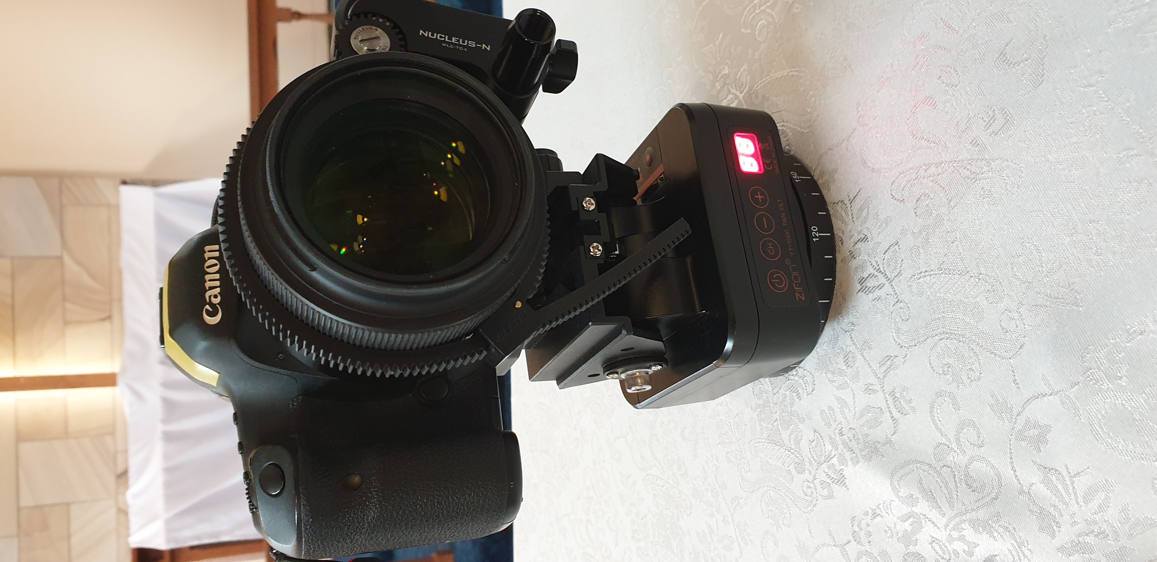
Today I had the chance to test out the pan tilt head. At a range of ~25 metres, the unit didn’t seem to respond to the RF remote, but over WiFi I had perfect control! Paired with the Tilta Nucleus-Nano wireless follow focus, I essentially had a Pan Tilt Zoom/Focus system for AUD$500. I was concerned about the loading (1.75kg camera system + torque), but after offsetting the camera balance the PT unit held up!
Having field-tested it, there are a few changes that I need to make.
- Allow the X and Y axis controls to be flipped (left moves the unit right, etc)
- Speed controls