I realise I’m starting to have quite a lot of smart home posts…
No I am not an IoT channel, I just want to excessively put WiFi capabilities on everything I can 😉
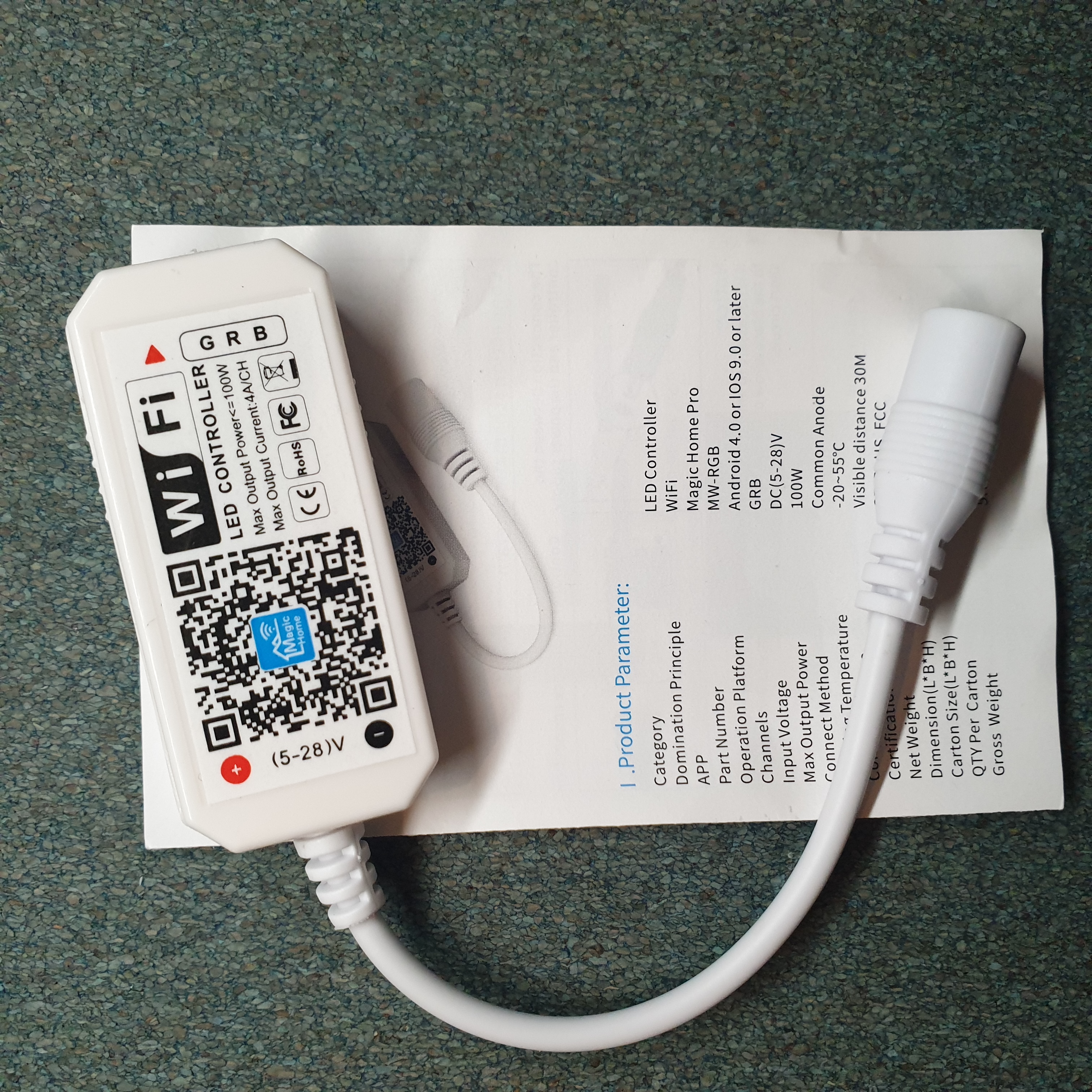
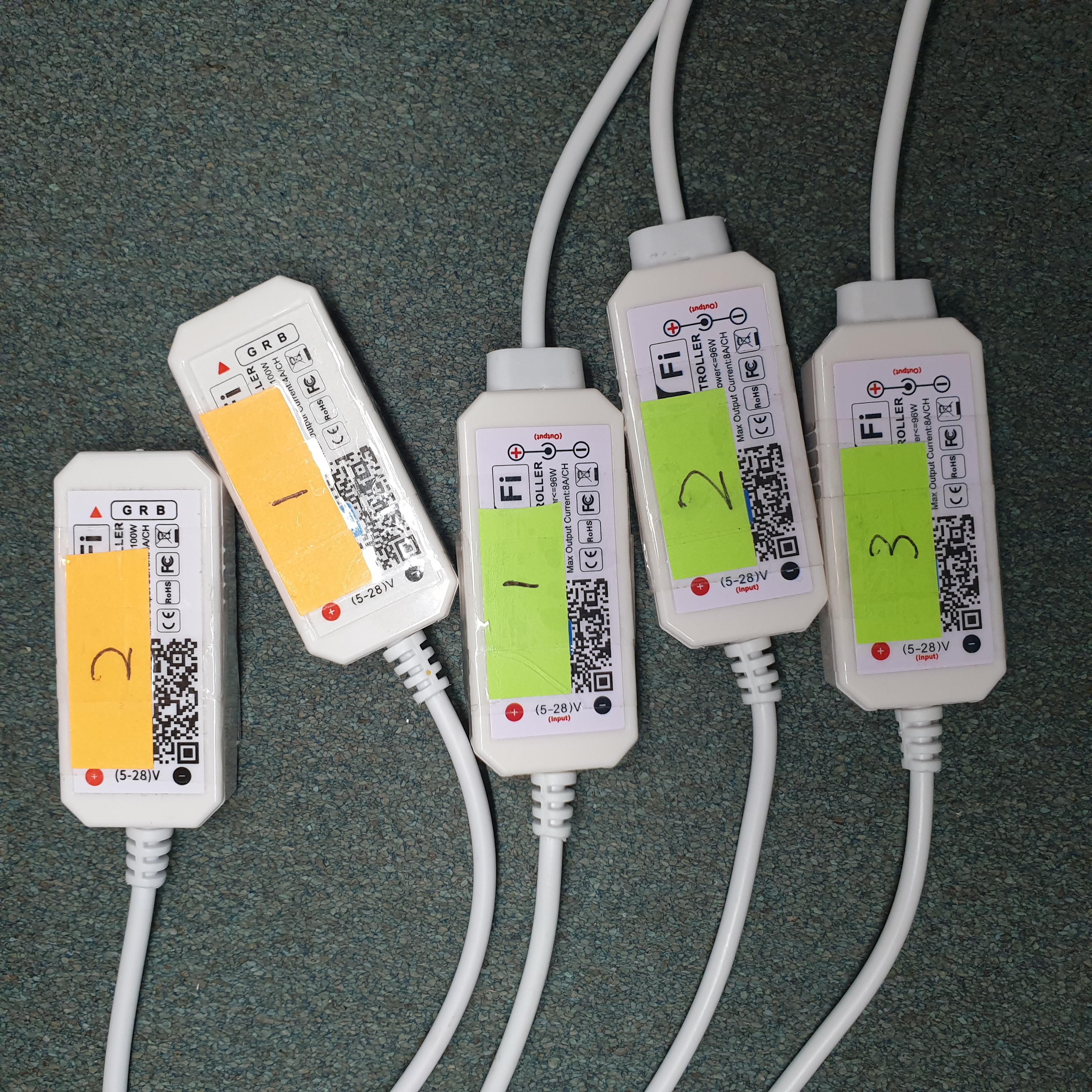
I have a bunch of these MagicHome WiFi LED controller devices which I bought a couple of years back when I wanted to add some nice ambient lighting to my rooms.
I got the controllers, I got the LED strips … but yeah it never happened as I got carried away with other things in life… My brother ended up using a couple for his own room.
With the majority of the initial stages of my thesis done, I have a bit of breathing space before I get carried away with other things - So I decided to come back to these devices, and address the biggest issue that my brother (and a lot of other users) have observed - how sluggish and volatile these devices work when integrated with HomeAssistant. If you change the settings too fast (i.e. change brightness, or toggle the power), the device stops communicating and you have to manually power cycle the device to regain connection (or wait like 2 minutes?).
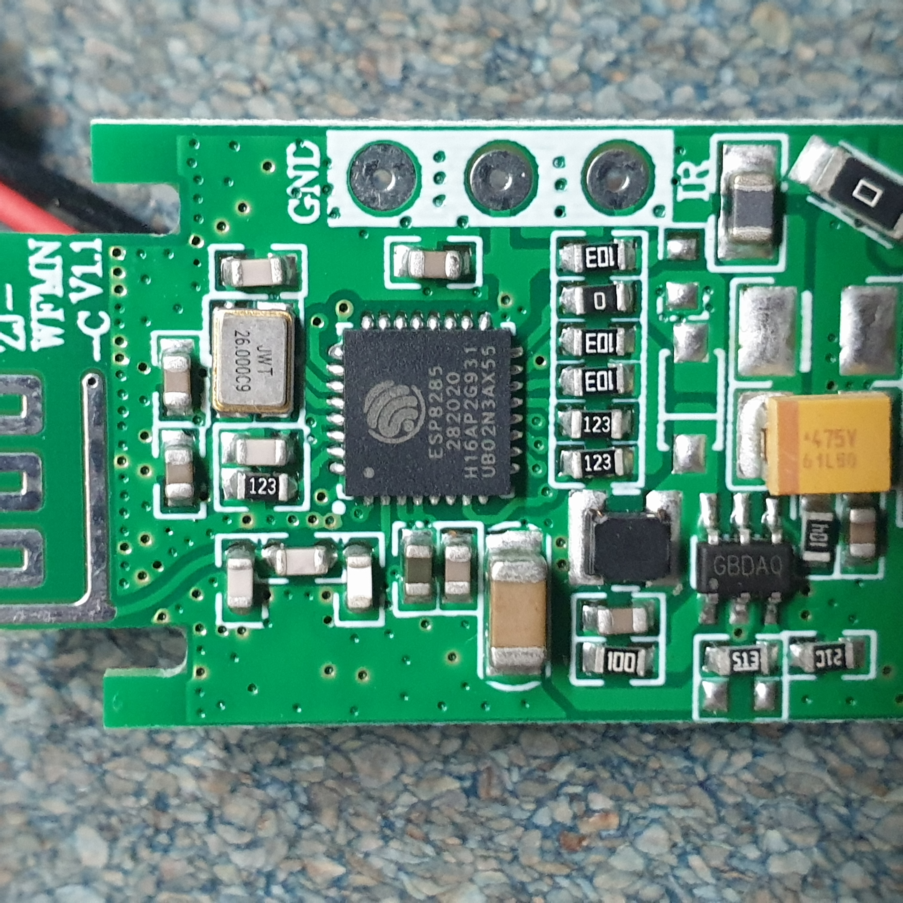
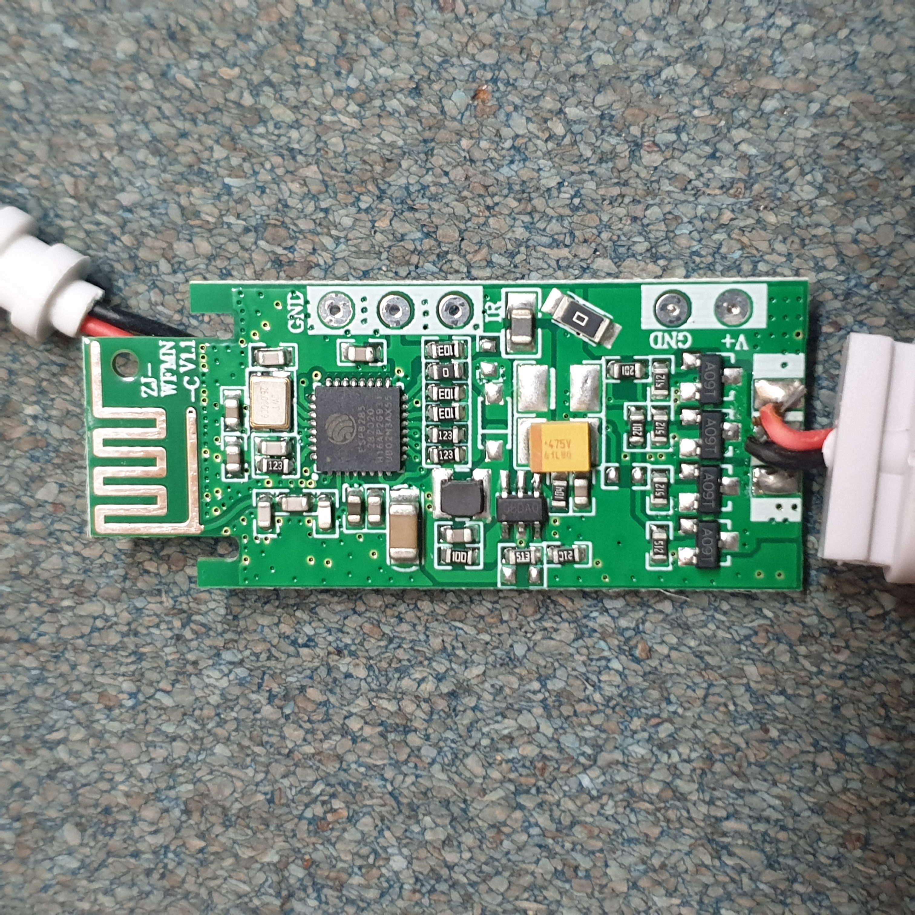
Thankfully a bunch of people have already successfully attempted to solve this by flashing more stable firmware onto the device ([1] [2] [3]). This works because inside the device is an ESP8285, a SoC that is compatible with software like Tasmota or ESPHome. Additionally, installing these custom firmwares also decouples the device from cloud services - which is a huge plus when it comes to privacy and network security!
Note: Supposedly, more recent versions of this device no longer use the ESP8285, but rather some chip with the model code S9070B.
Do not purchase the variant with the board revision ZJ-WFMN-E!
Find the one which ends with
-A(or-C) and purchase that one
Opening Up The Device
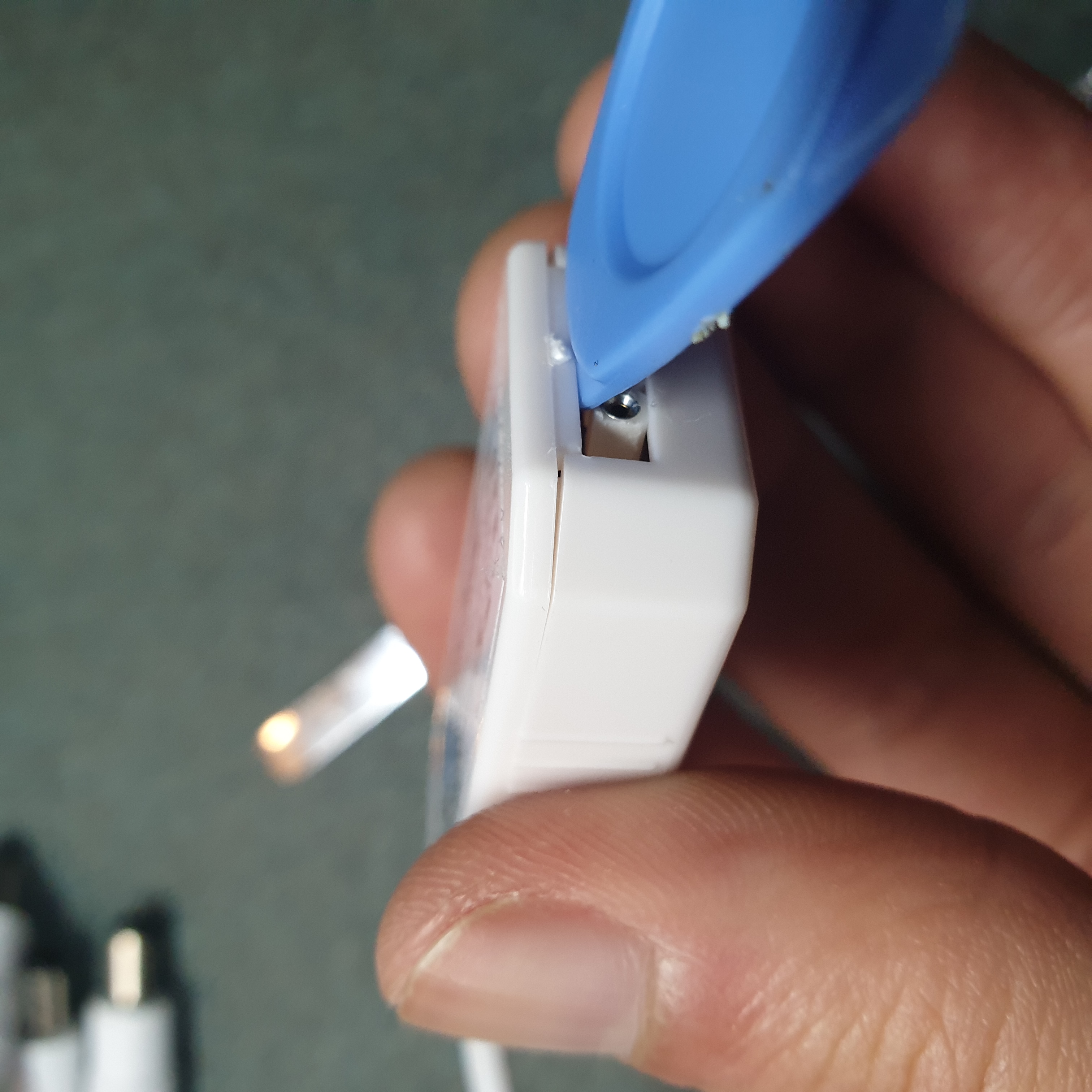
The lid of the case is held by four clips on the long sides of the device.
Just get a spudger / something flat and make your way around to release the clips
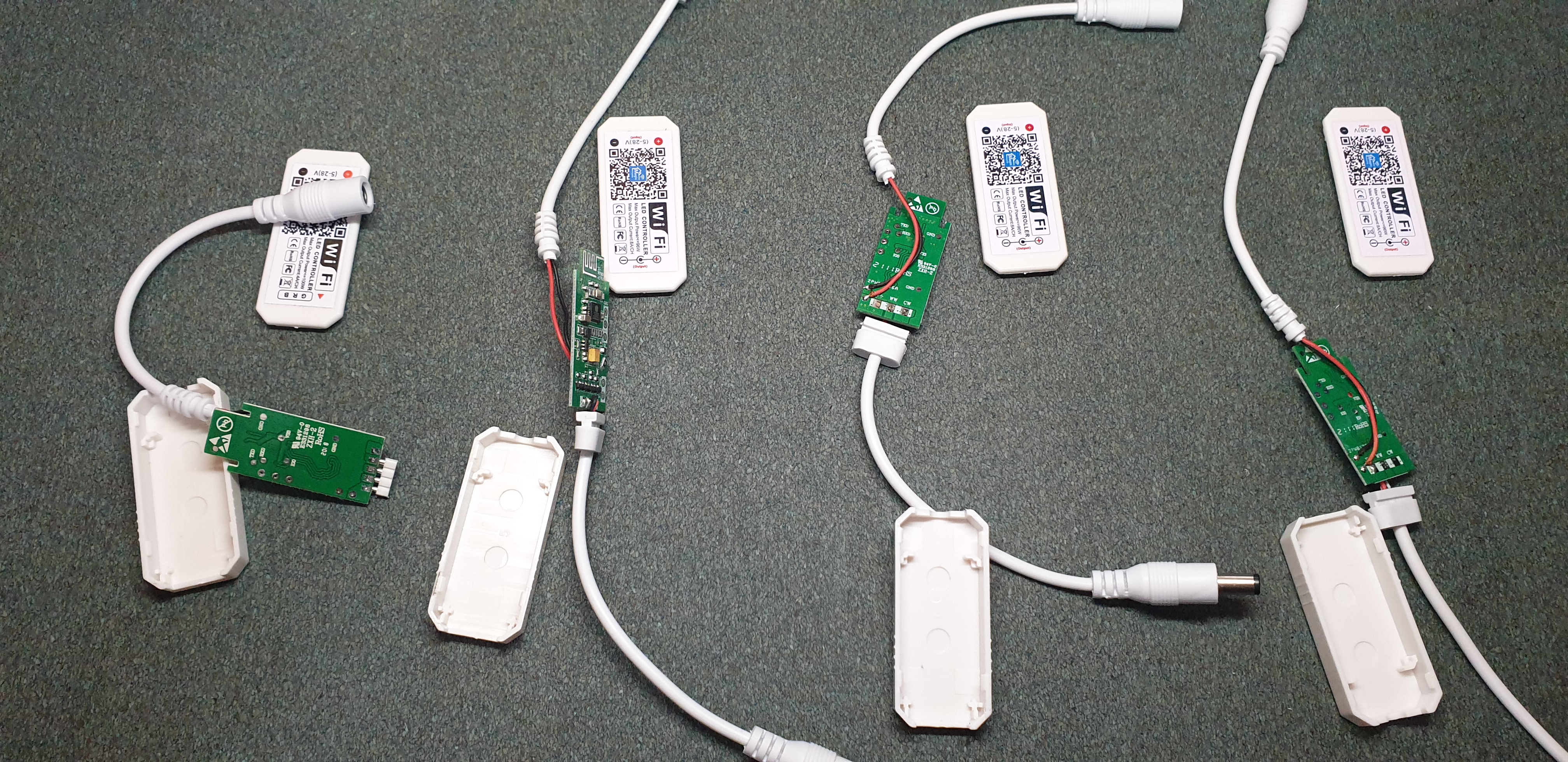
Circuit Board
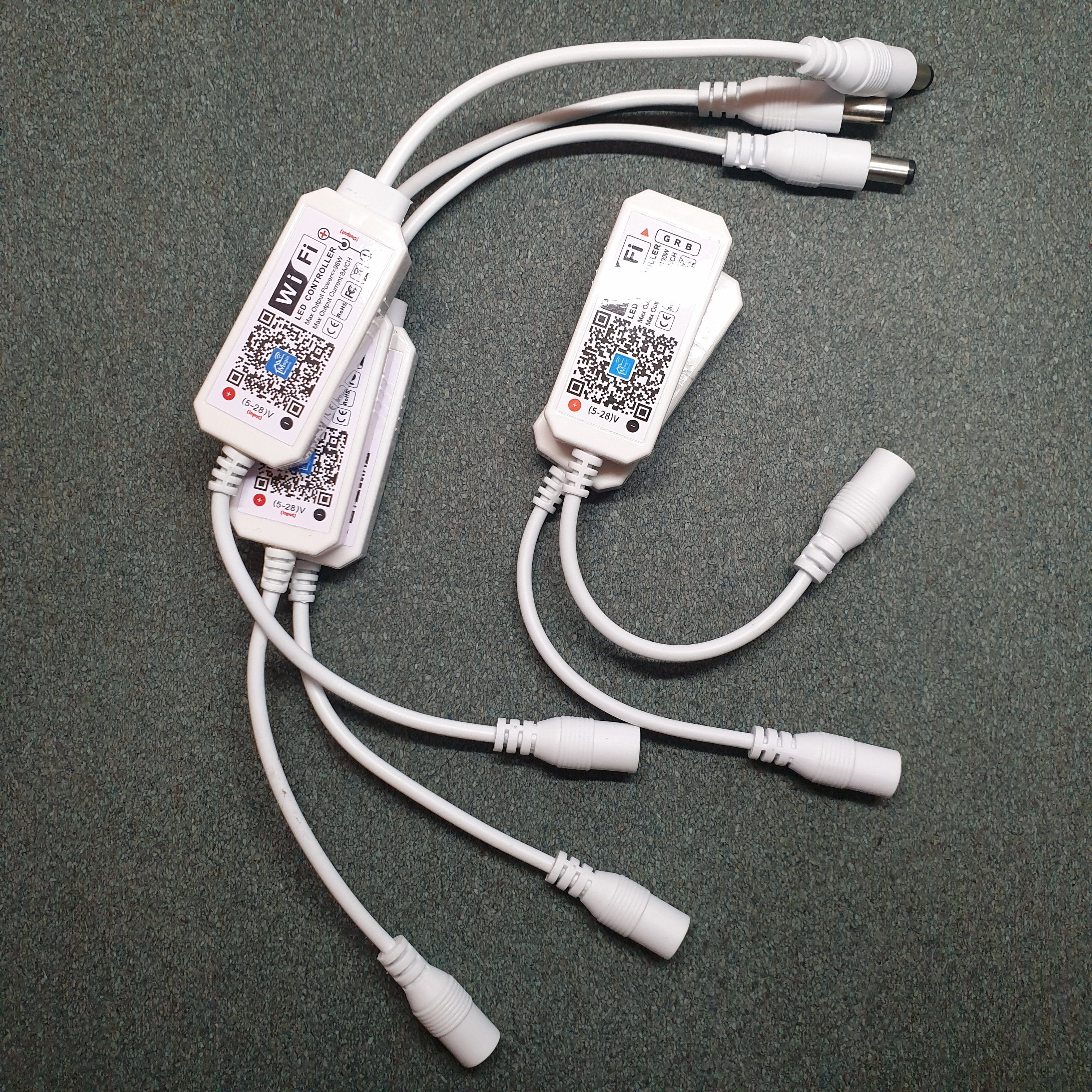
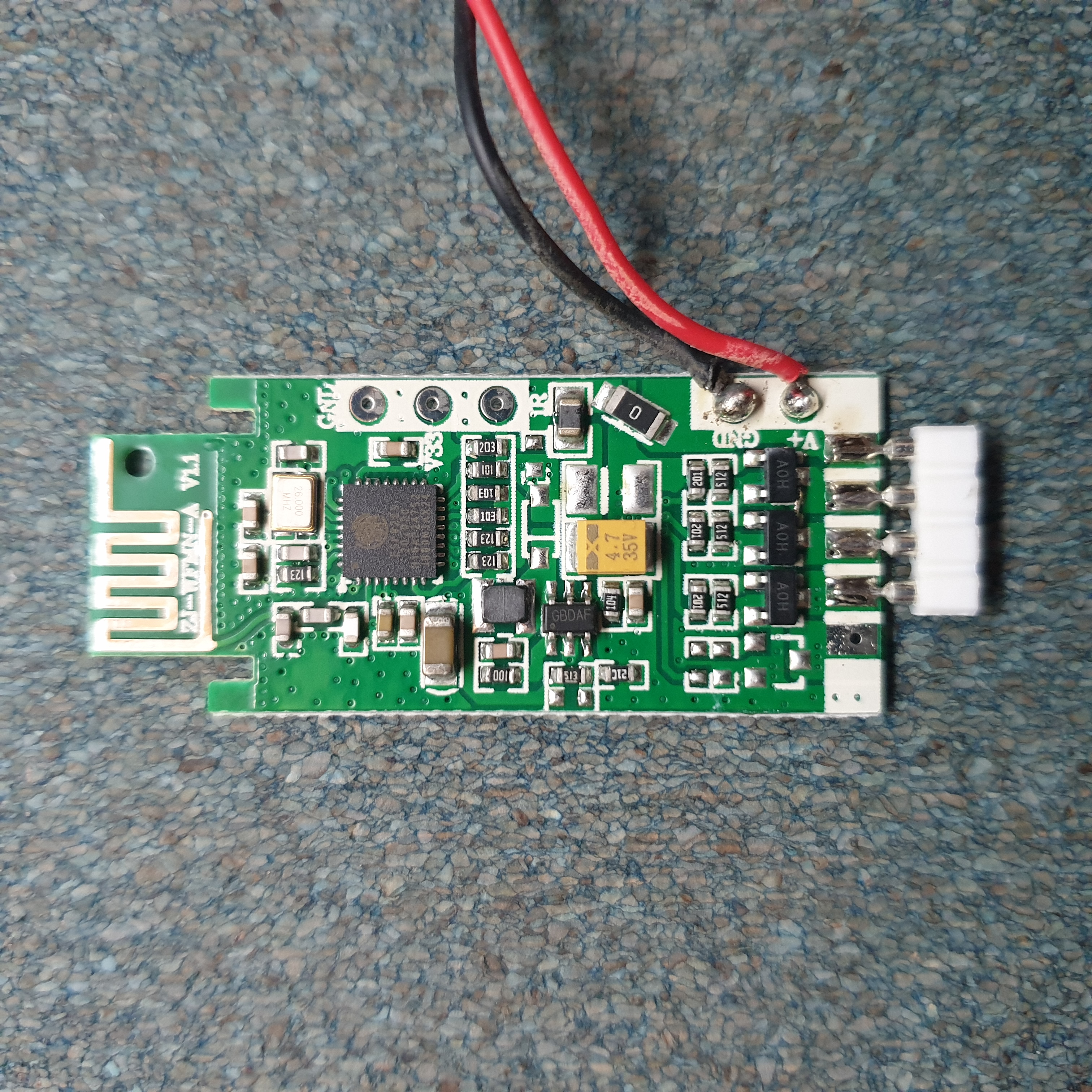
MW-RGB | ZJ-WFMN-A | RGB WiFi LED Controller
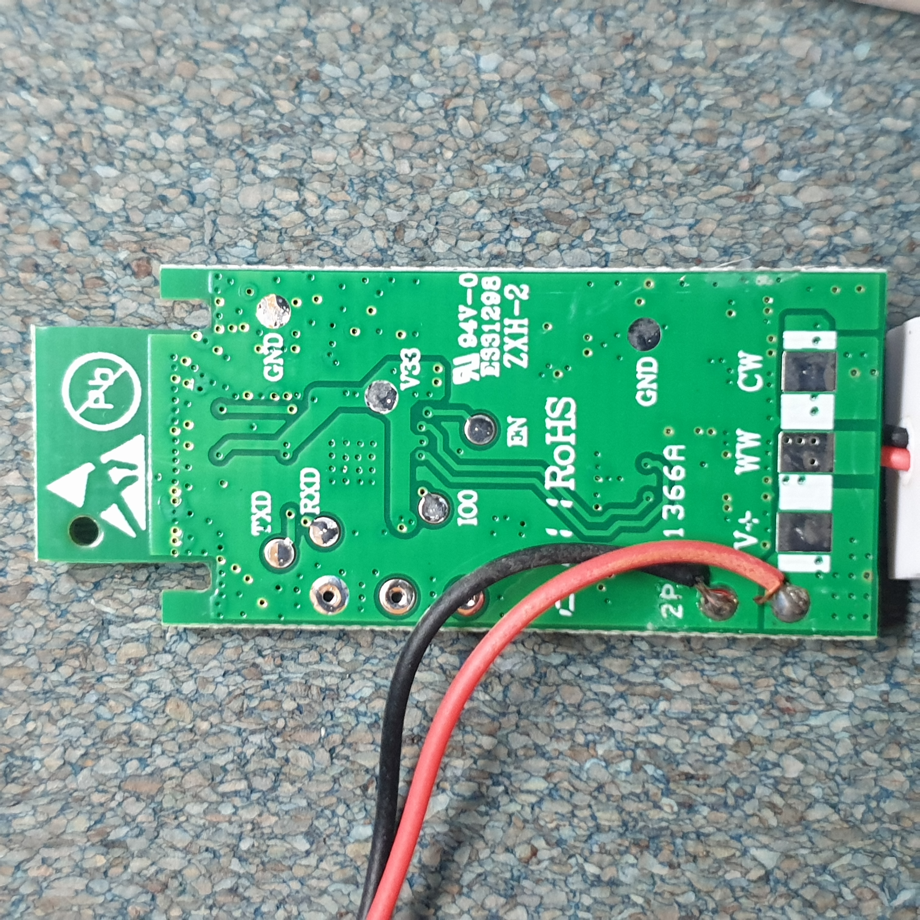
MW-S | ZJ-WFMN-C | DC WiFi LED Controller
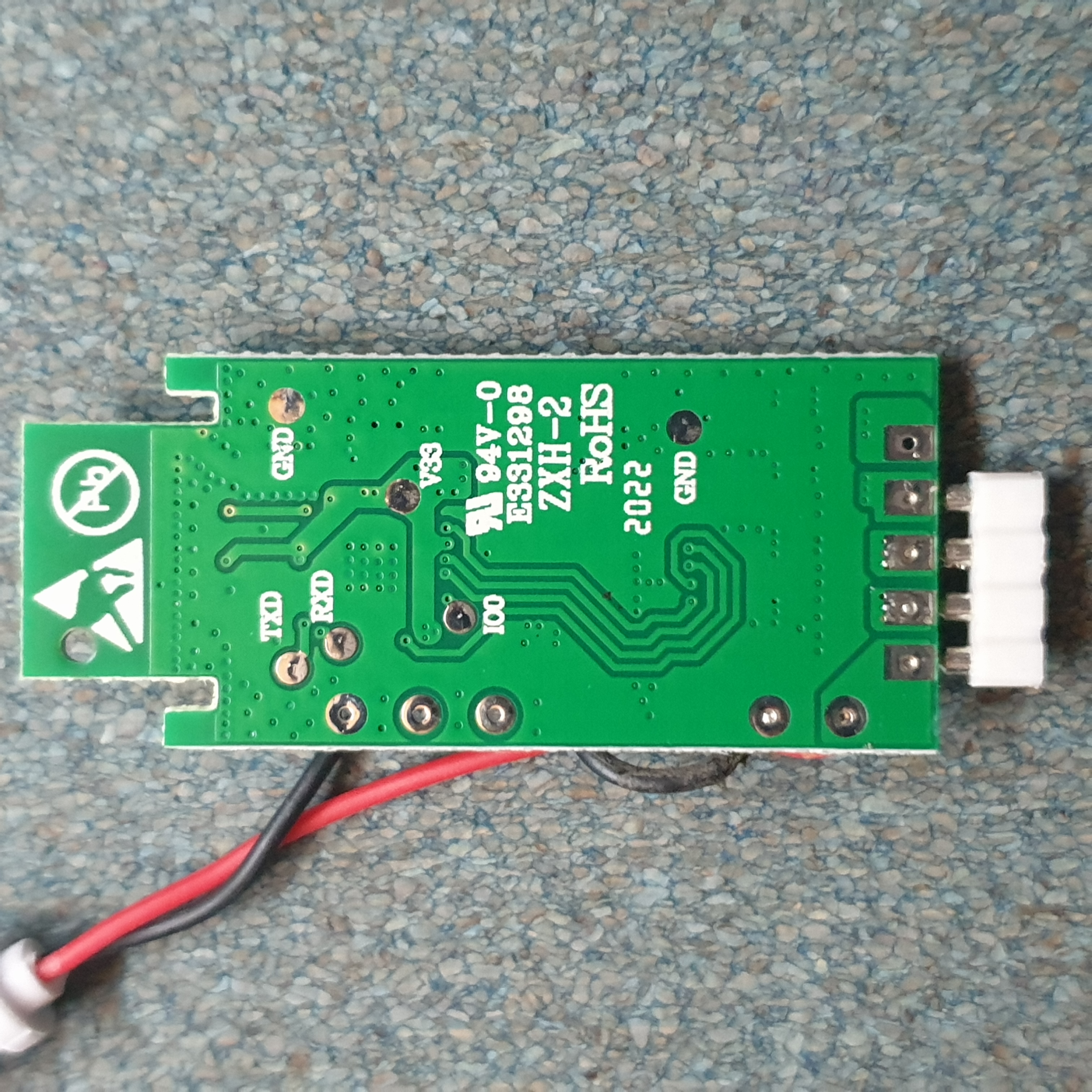
Pins
On both units that I have, there are a couple of solder pads.
TXD- Serial TransmitRXD- Serial ReceiveIO0- Bootloader Download Mode (When pulled to ground during boot)V33- +3.3V- 2x
GND
On the ZJ-WFMN-C there is also an EN pin which resets the device when pulled to ground
Wiring
To flash the ESP8285 device, we want to connect our serial programmer - I’m using some generic USB to UART Serial cable. Most guides that I glossed over said to solder the TXD, RXD, V33, GND, and IO0 pads to some jumper wires and attach them to your programmer - but I’m kinda lazy and not bothered to solder/desolder/resolder five wires a bunch of times…
Also, my USB to UART adapter communicates with a 5V logic level - which if connected to the ESP8285 (which operates at 3.3V) will fry it.
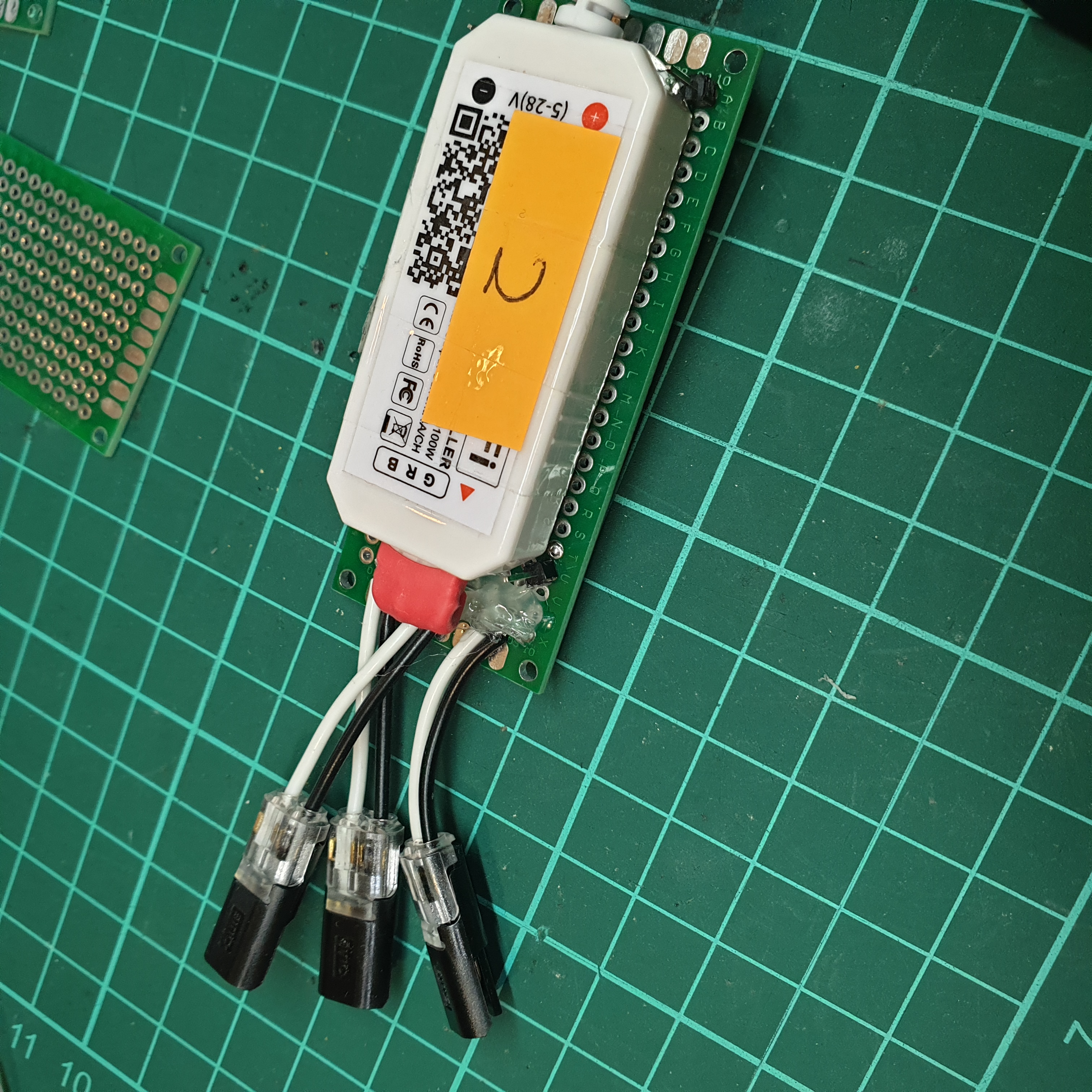
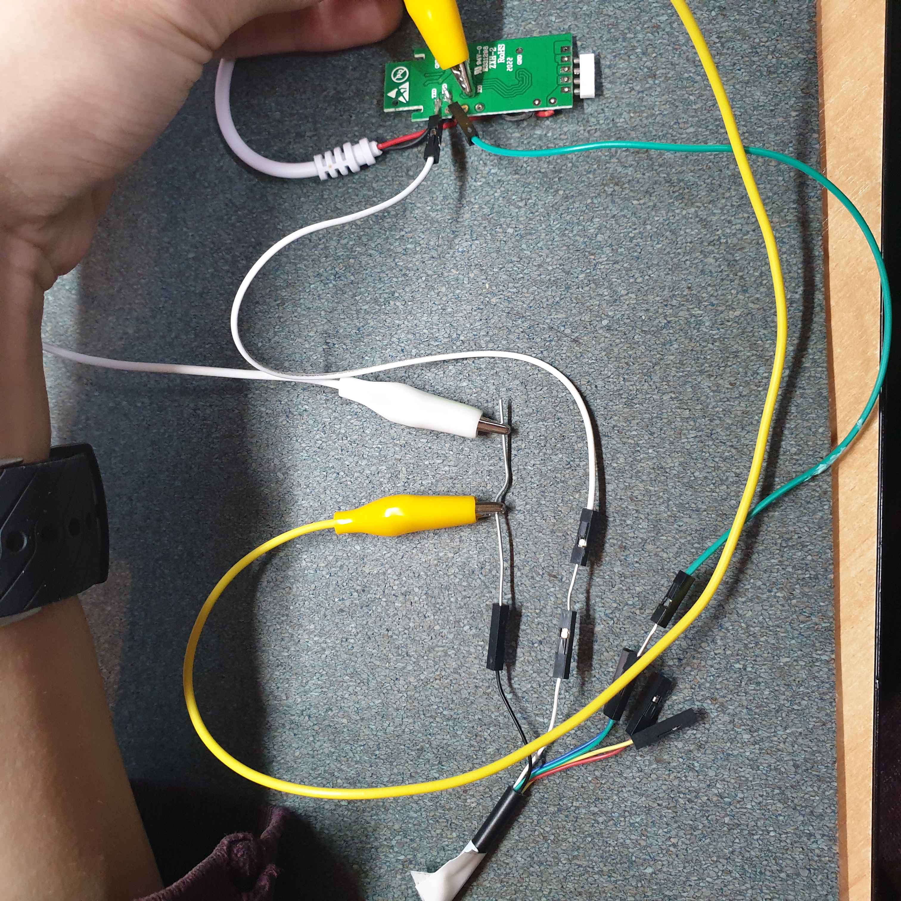
So here’s what I did instead
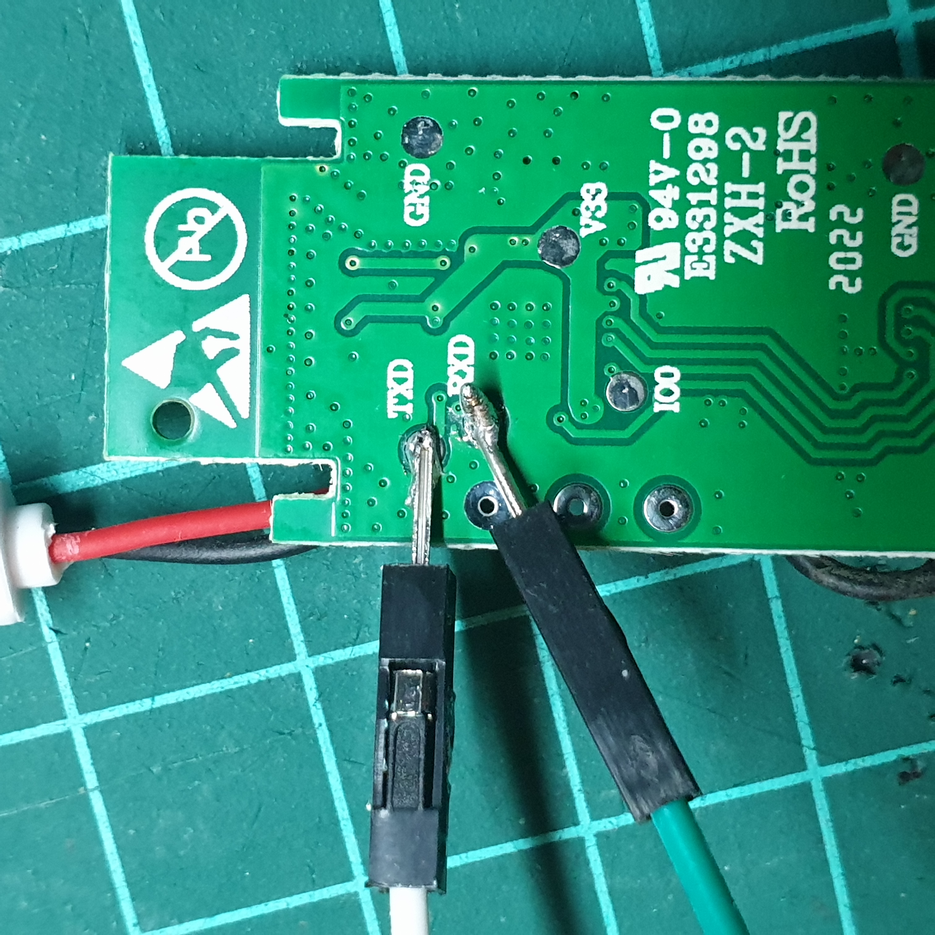
Note that the programmer TX pin is connected to the
RXDpad, and the programmer RX pin is connected to theTXDpad!
If you get this opposite order wrong, no harm! Just swap them around!
- Programmer TX ->
RXD - Programmer RX ->
TXD V33GND- Programmer GND - Bridged with the DC jack (electrically they’re inherently connected, but I added this for good measure)
IO0- Bridged with the DC jack
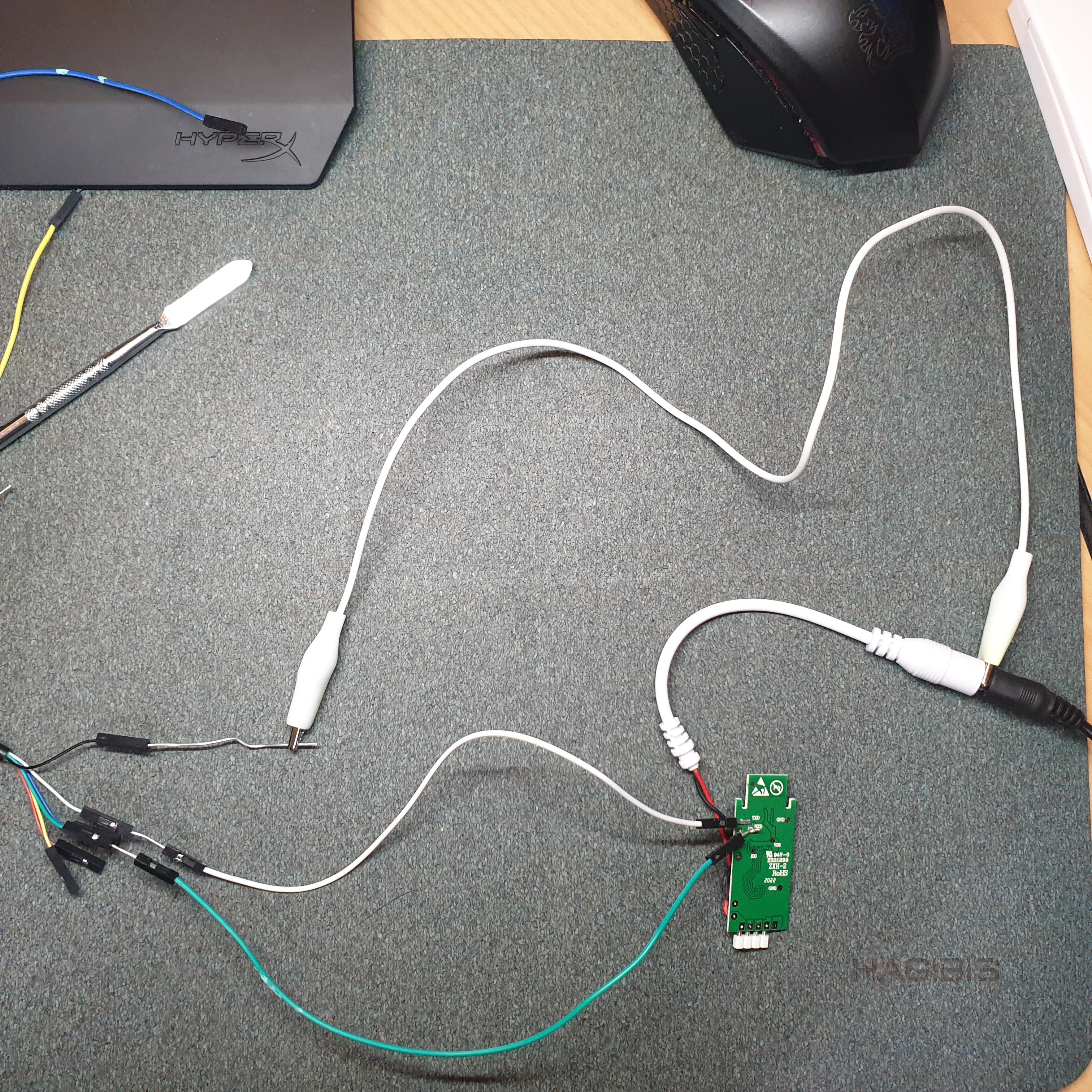
- The 3.3V that should be applied onto
V33comes from the onboard DC power input voltage regulator that steps down the 5V-28VDC input to 3.3VDC, so no need for me to make any voltage divider or something of the likes GNDis also connected with the DC power input, so connecting the DC barrel jack will inherently provide the ground reference- As
IO0only needs to be momentarily grounded (can be left permanently grounded for flashing purposes), I decided to just connect an alligator clip (yellow) to the ground node, and just make contact to theIO0pad with the other end whilst powering on the device.
Wait… did you just shove an alligator clip over the DC power supply? And are those paperclips!??!?
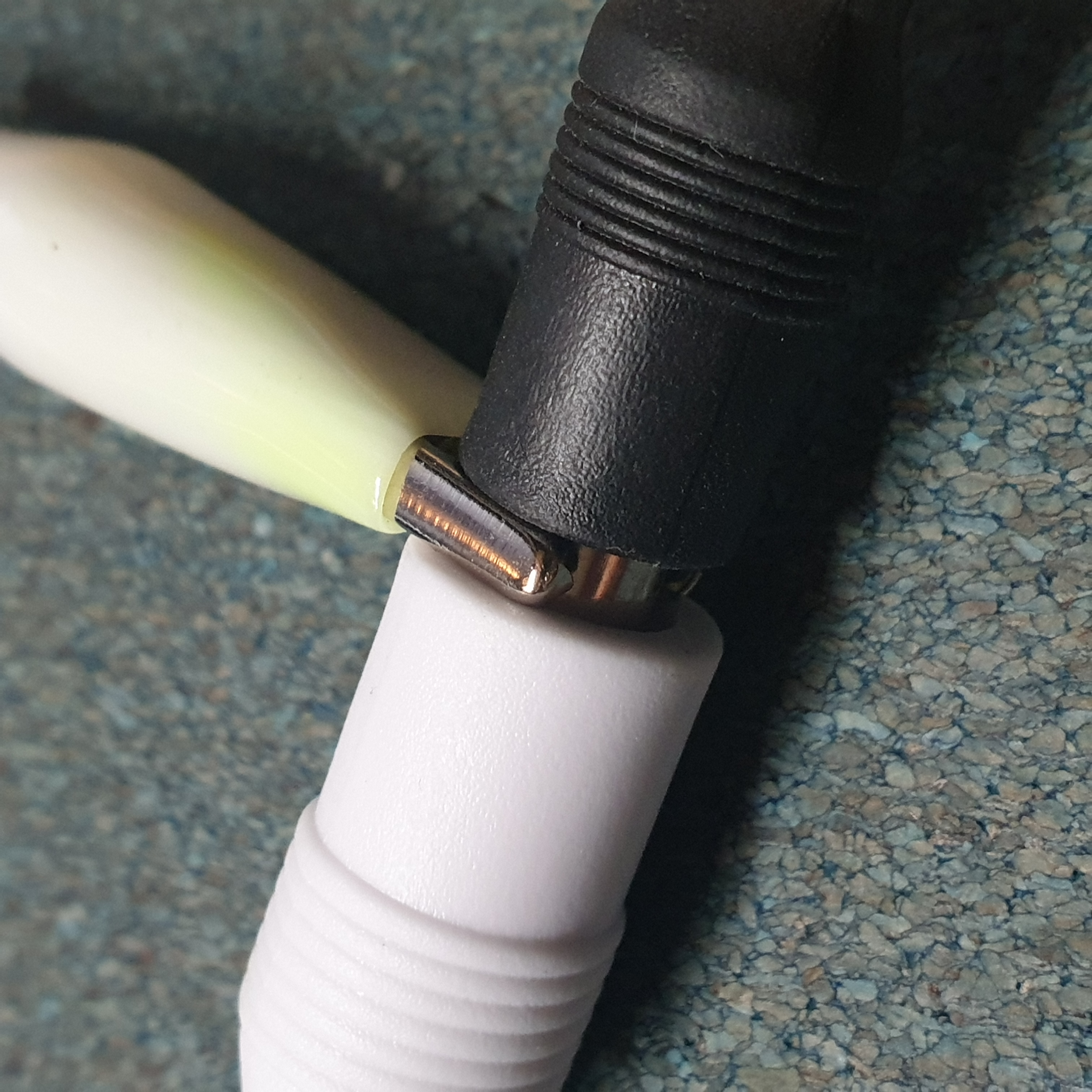
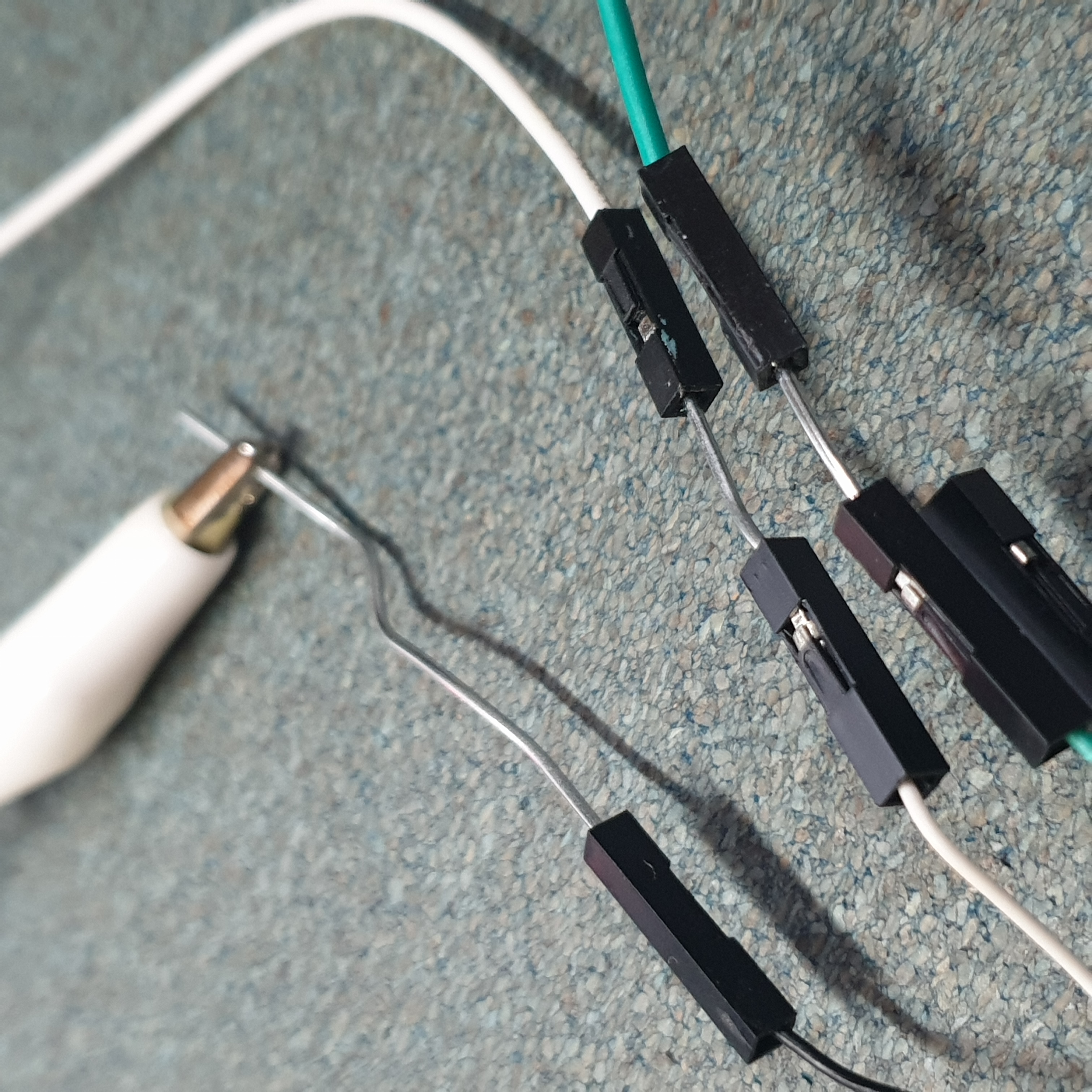
Of course not! I’ll never jeopardise my health for convenience Yes, and yes 😇. Alligator clips and paperclips are the bane of my electrical engineering existence
Flashing
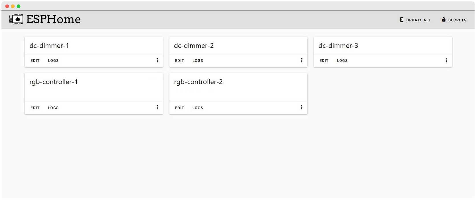
In ESPHome, I created a new device targeting the “Generic ESP8285 module” board, and entered in some initial settings (like the wireless network settings).
With ESPHome, once the device has the associated firmware, you can remotely perform OTA updates and configuration!
After the firmware binary was compiled, we can easily flash the device with the ESPHome Flasher tool.
This is a rather straightforwards process
- (Connect the
TXDandRXDpins, and optionallyGND) - Ground the
IO0pin to enter the bootloader download mode - Attach the DC power (i.e. supply power)
- (Wait a few seconds, then remove the connection to
IO0)- (Or keep it there, up to you!)
- Open the ESPHome Flasher utility
- Select the correct serial port
- Select the downloaded firmware
- Press [Flash ESP]
- …
- Profit $$$
You might not see any output after the flashing is completed - just perform a power cycle and you should be good.
Configuration
The pinout of this board is well-known, so there’s no probing needed to be done to find which pin corresponds to what output :)
- MW-RGB | ZJ-WFMN-A | RGB WiFi LED Controller
- G - GPIO5
- R - GPIO12
- B - GPIO13
- MW-S | ZJ-WFMN-C | DC WiFi LED Controller
- Output - GPIO12
With these pinouts, we can create a simple configuration for each device
ZJ-WFMN-A Configuration
Instead of using these controllers as RGB strip controllers (I don’t particularly always want RGB…), we can use each output independently, effectively turning this device into a three-channel DC dimmer.
Note that each pin output is actually the negative end, with the supply (positive) coming from the common output.
ZJ-WFMN-C Configuration
After updating the configurations to each device, we can now control the devices in HomeAssistant.
It’s way more responsive and doesn’t intermittently become unresponsive!
Hopefully sometime in the future I’ll actually end up using them, otherwise my brother can now benefit from these device upgrades :)
Good hack, I rate 7/8 would do again and again