It gets kinda hot in Australia - the dry sort of heat (which is arguably better than humid heat). Having been at my cousin’s place last year to celebrate Christmas, I saw that they had bought a few “fans” from a company called Vornado. Now I say “fans” because their line of products are advertised as “air circulators” rather than “fans”. Whether or not you (or we) believe(d) in the physics of an “air circulator” ([1] [2]) - it was definitely able to keep my cousins and I cool during the heat!
Given the positive hands-on experience I did some research and ended up buying one for myself (a Vornado 660). Whilst I still haven’t decided if aiming it at the ceiling is really more effective than just directing it towards me (whole ‘air circulator’ errata), Vornado’s claims to push air reaaaal far definitely holds true!
Now one thing I don’t like about this Vornado 660 is that when you turn it on; it defaults to full power (level 4) regardless of what the previous state was. This is sort of inconvenient as it’s quite noisy at full power (at least when using it near me [which again, isn’t its intended purpose]), and I have to press level 1 or 2 right after I turn it on.
Additionally, the device isn’t a ‘smart home’ appliance, meaning that I was unable to control it remotely through HomeAssistant, etc… (I mean, not everything needs to be a smart device… but hey!). Furthermore, connecting the device’s power plug to a smart power strip wouldn’t work due to the internal MCU always starting up on the “off” mode.
Novel Solutions
Full Power When Turned On
I could swap around the motor driver cables such that the default “level 4” pin on the MCU actually triggered the motor to operate at “level 1”. This would however change the functionality of the device (not like I care though).
Remote Control
So it seems that as of writing this post (22/10/2021), Vornado had released an Alexa-enabled model called the Vornado 660 AE. I guess I could have bought that instead.
Solutions
To solve these two issues at once it was time to whip out a microcontroller first search on Google to see if anyone else had done it already (and hopefully just copy their steps).
- This Reddit post had someone asking for mod ideas for the Vornado 660 (my model!), and one of the comments (plus my own research) mentioned someone using an RF relay ([demo] [log])
- Another link I found had one person using a Photon board to automate their Vornado 660 as a fireplace blower
Whilst the above attempts ended successful, it wasn’t in-depth enough for me to follow along (Plus they had different goals anyway). So finally, it was time to whip out a microcontroller open up the device and take a look at the existing circuitry.
Hands On
Btw I recorded everything I did for the fun of it - see here
Physical Case
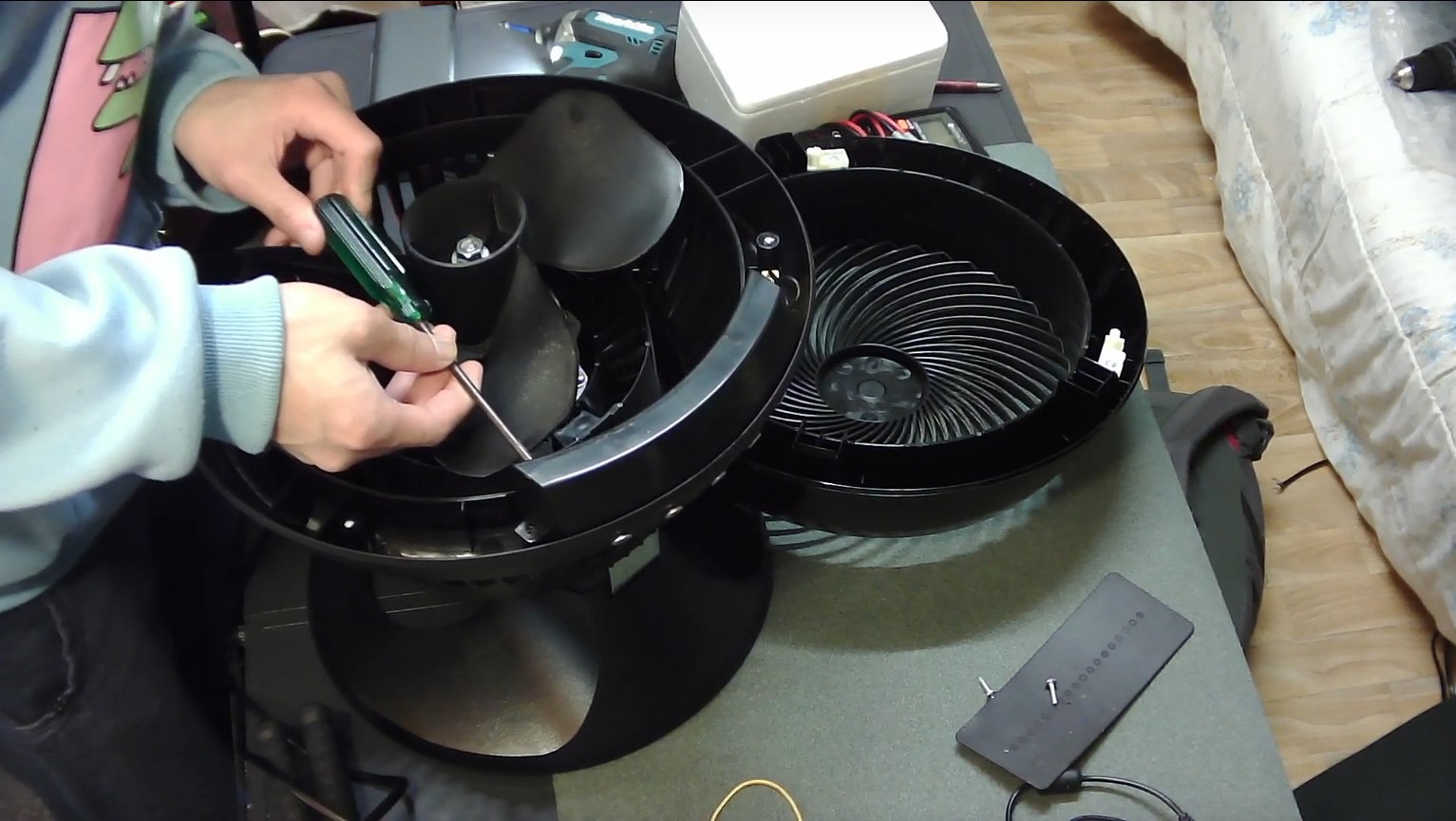
There are three Philips screws holding together the front grille and main unit. After the case has been removed, there are an additional five screws to remove in order to reveal the circuitry.
Circuitry
**Disclaimer: I am not an electrician, and I dropped out of Electrical Engineering - so I might be blabbering nonsense.
**I’m still alive though - so you can add that to my credibility?
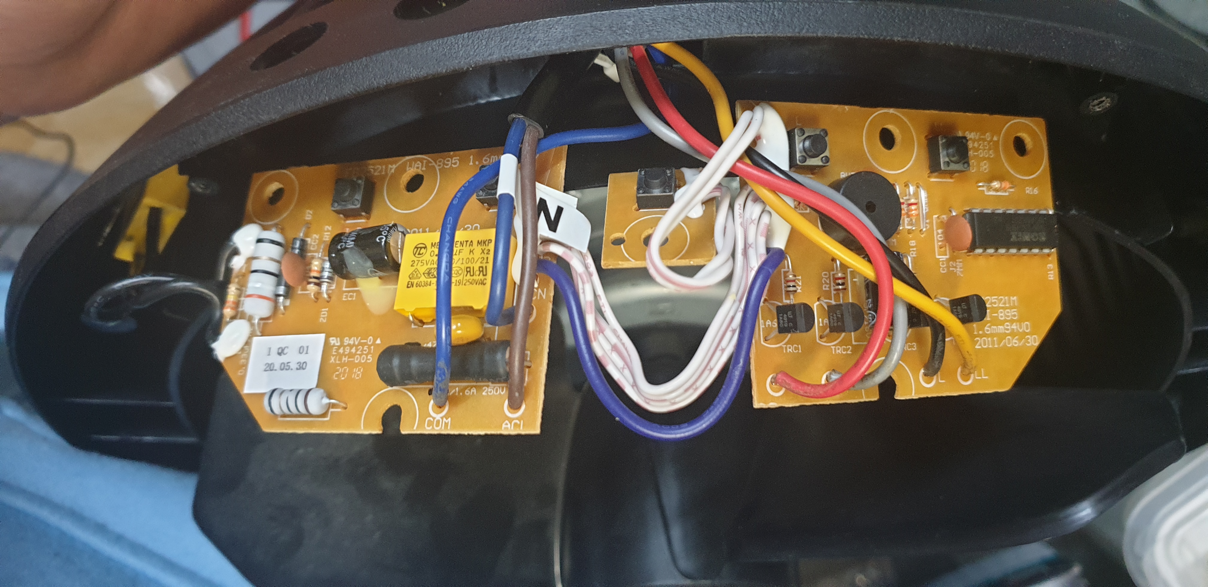
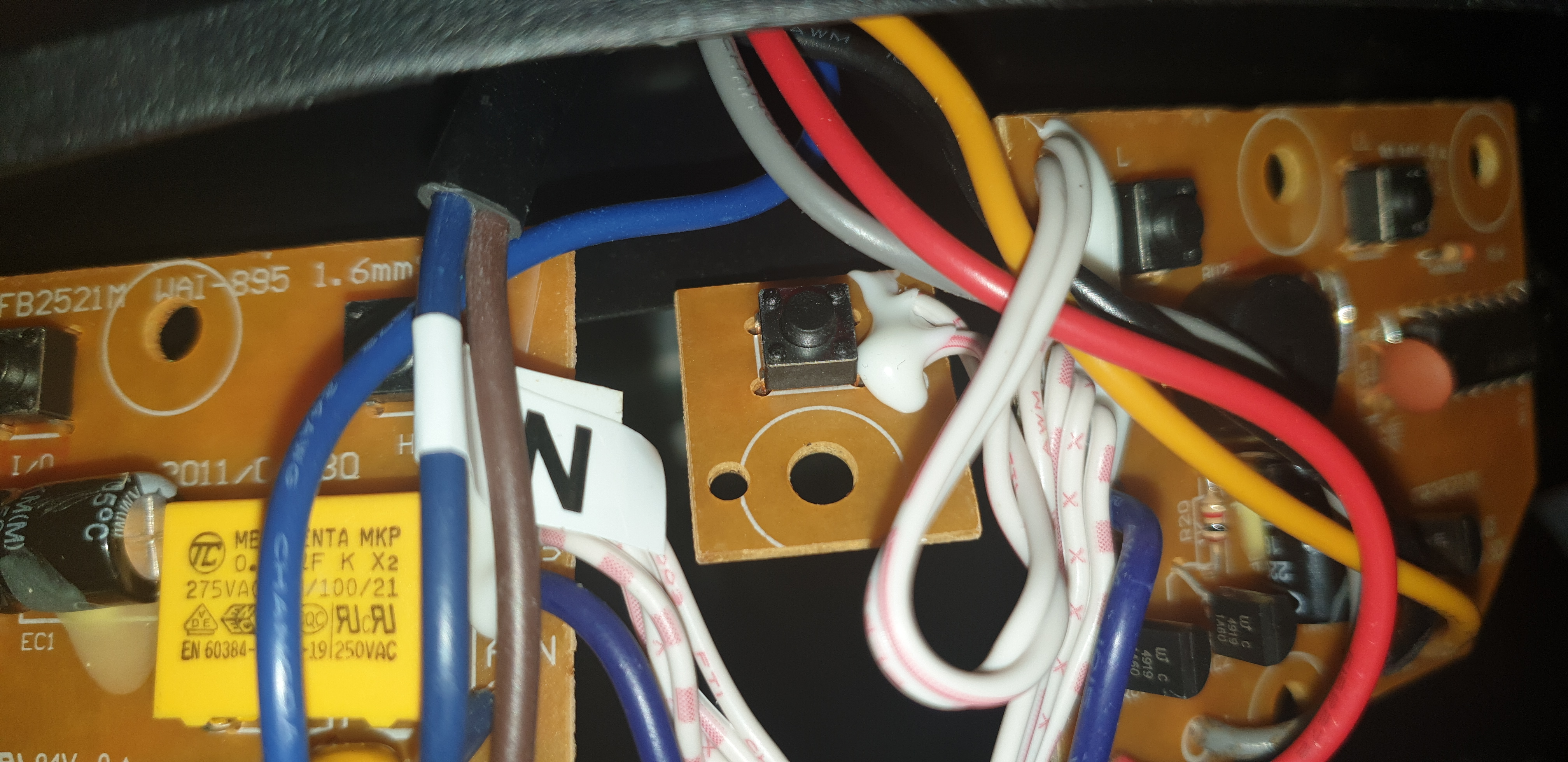
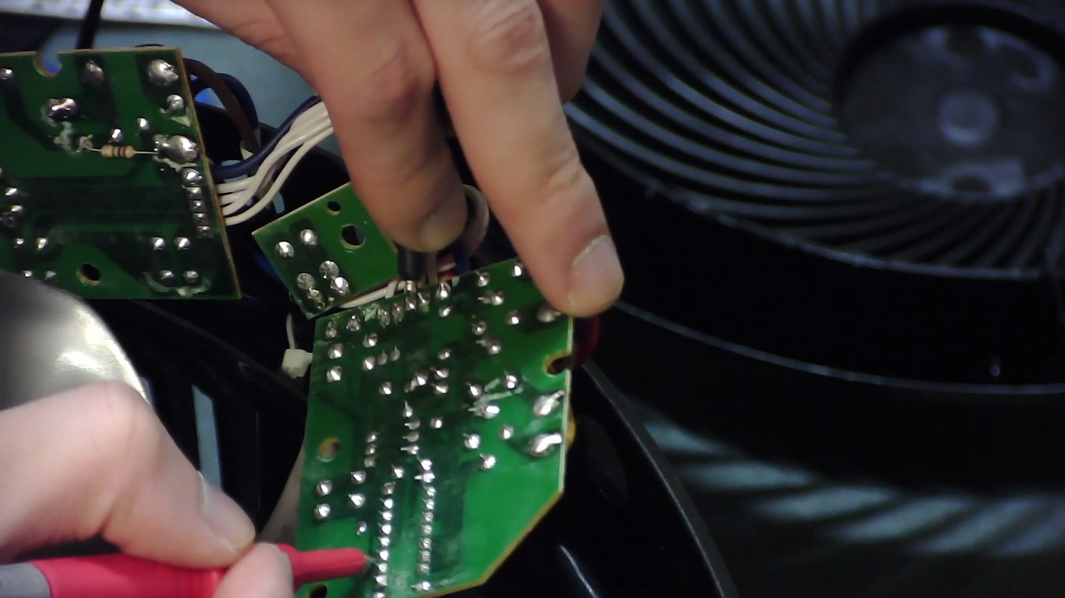
The circuit board is split into three boards (presumably to physically fit into the case) (although I feel like a single board would have also been possible).
Each board contains some of the push buttons (activated on LOW) for the power and mode switches, which all eventually connect to the MCU on board C (right-most).
Board A
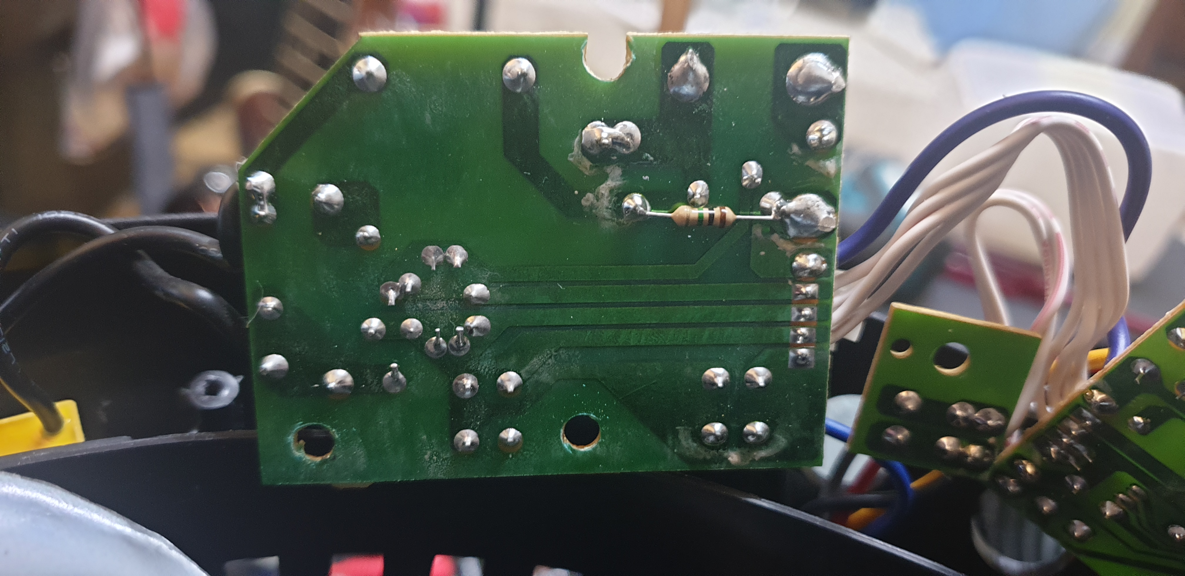
Board A contains a bunch of power components to take in the 240VAC and provide 5VDC to the MCU on board C.
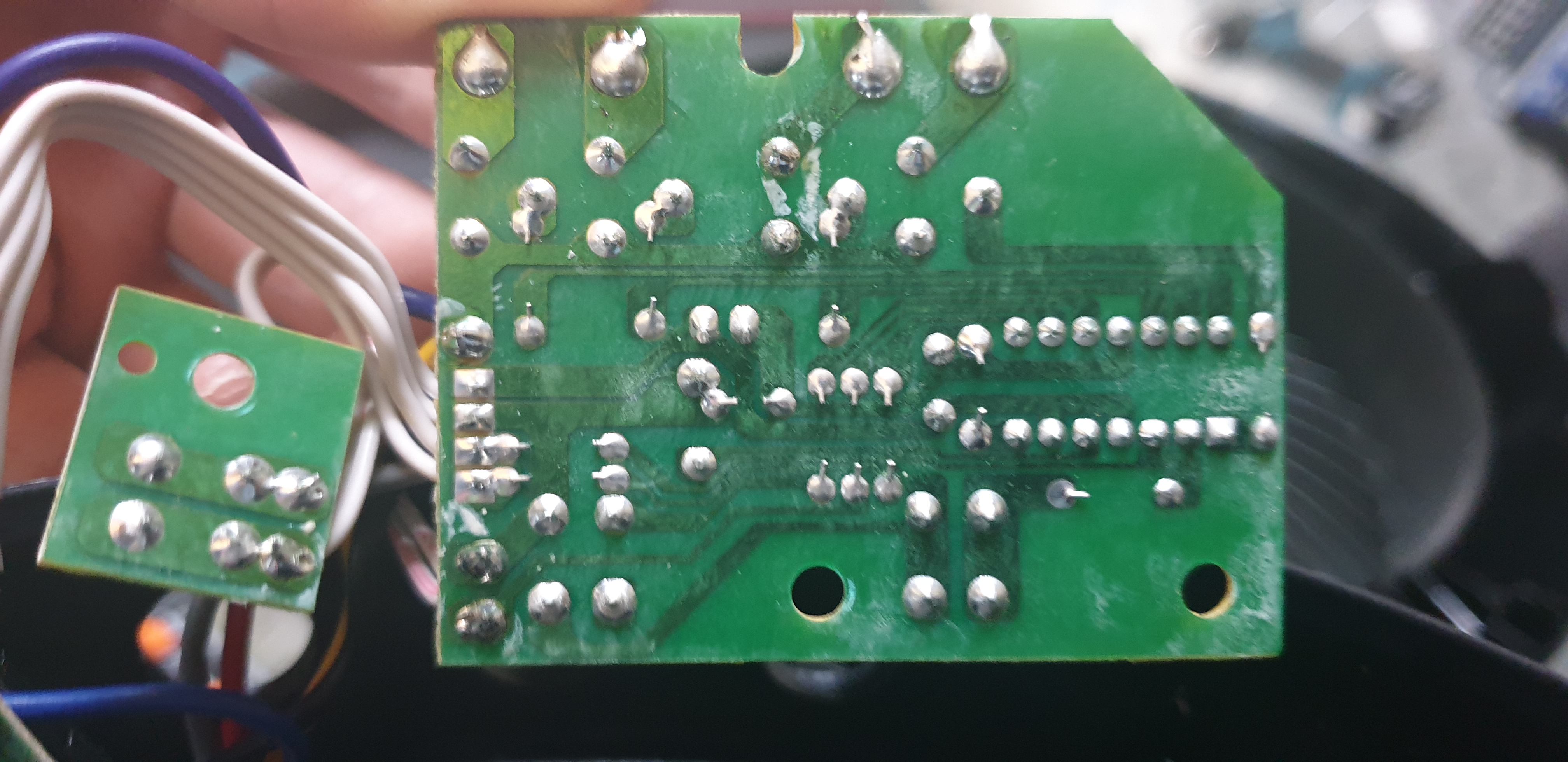
Board B
Board B just contains a single push button for fan level 3
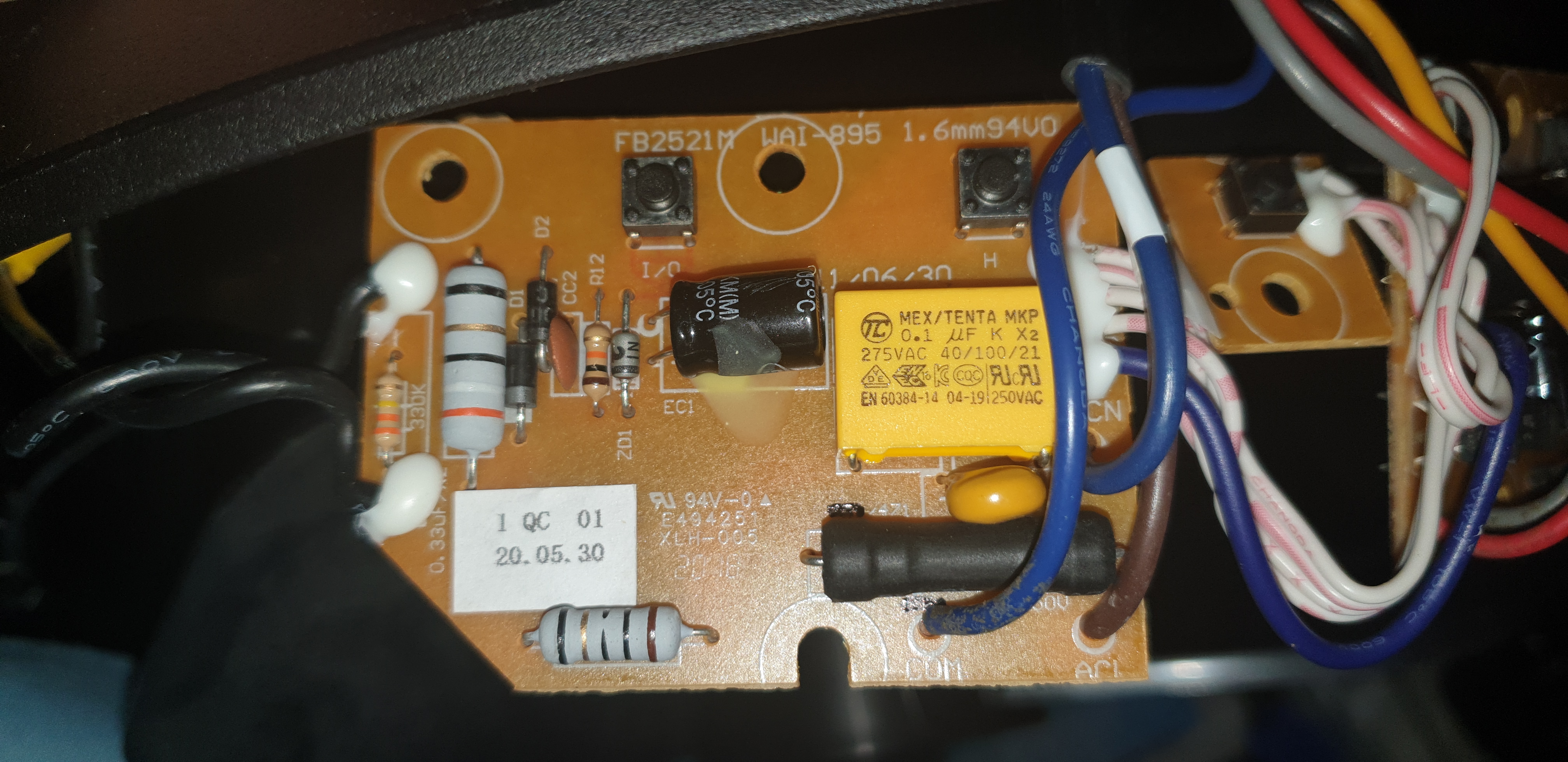
Board C
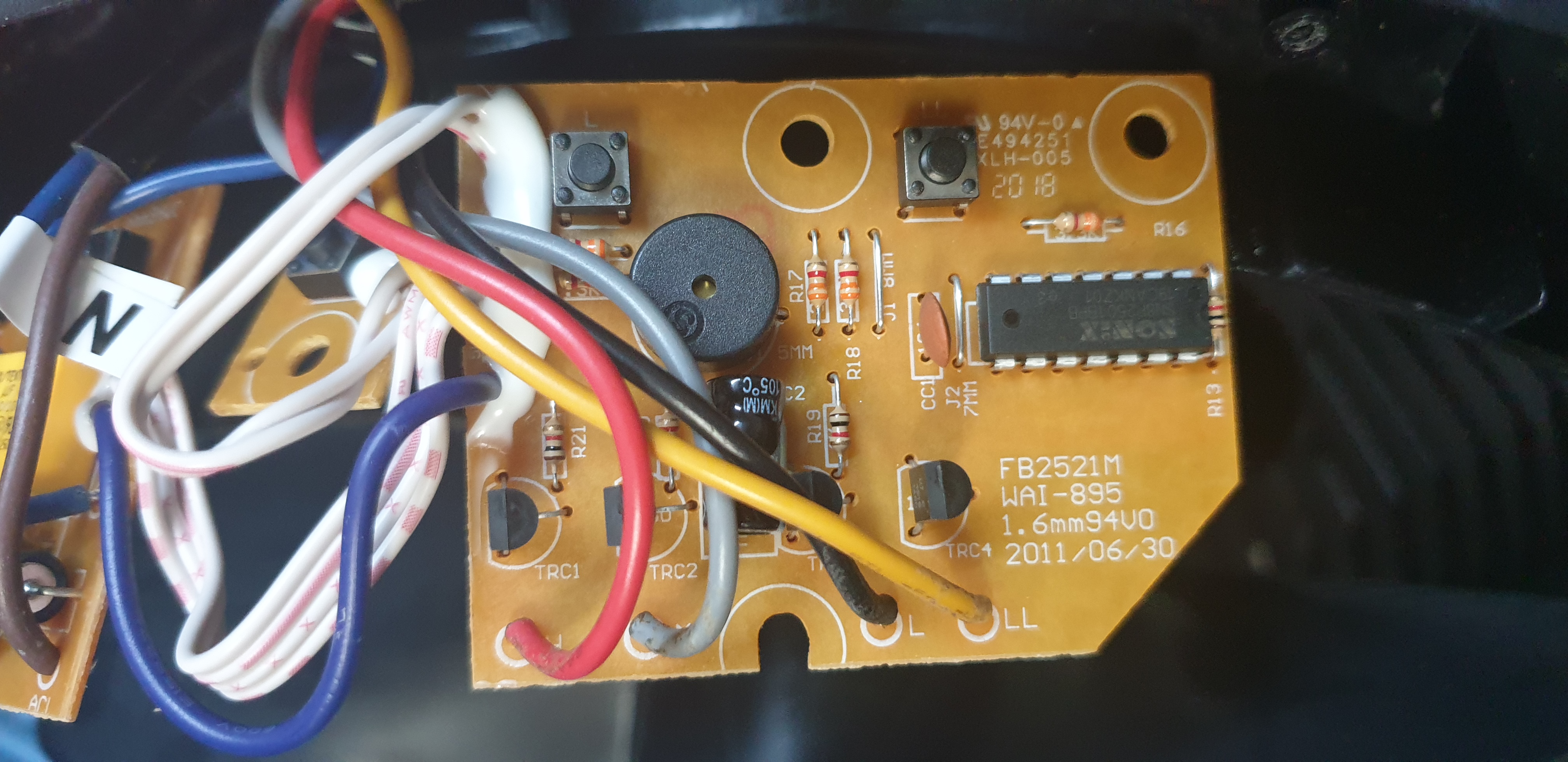
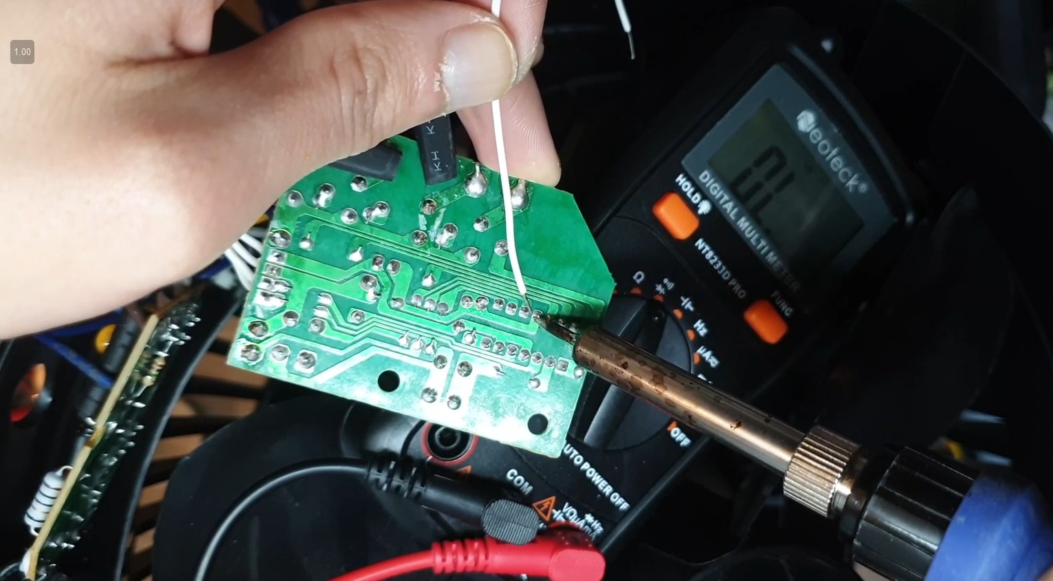
Board C is the most interesting of the three (at least in my opinion), and contains the MCU for the Vornado 660.
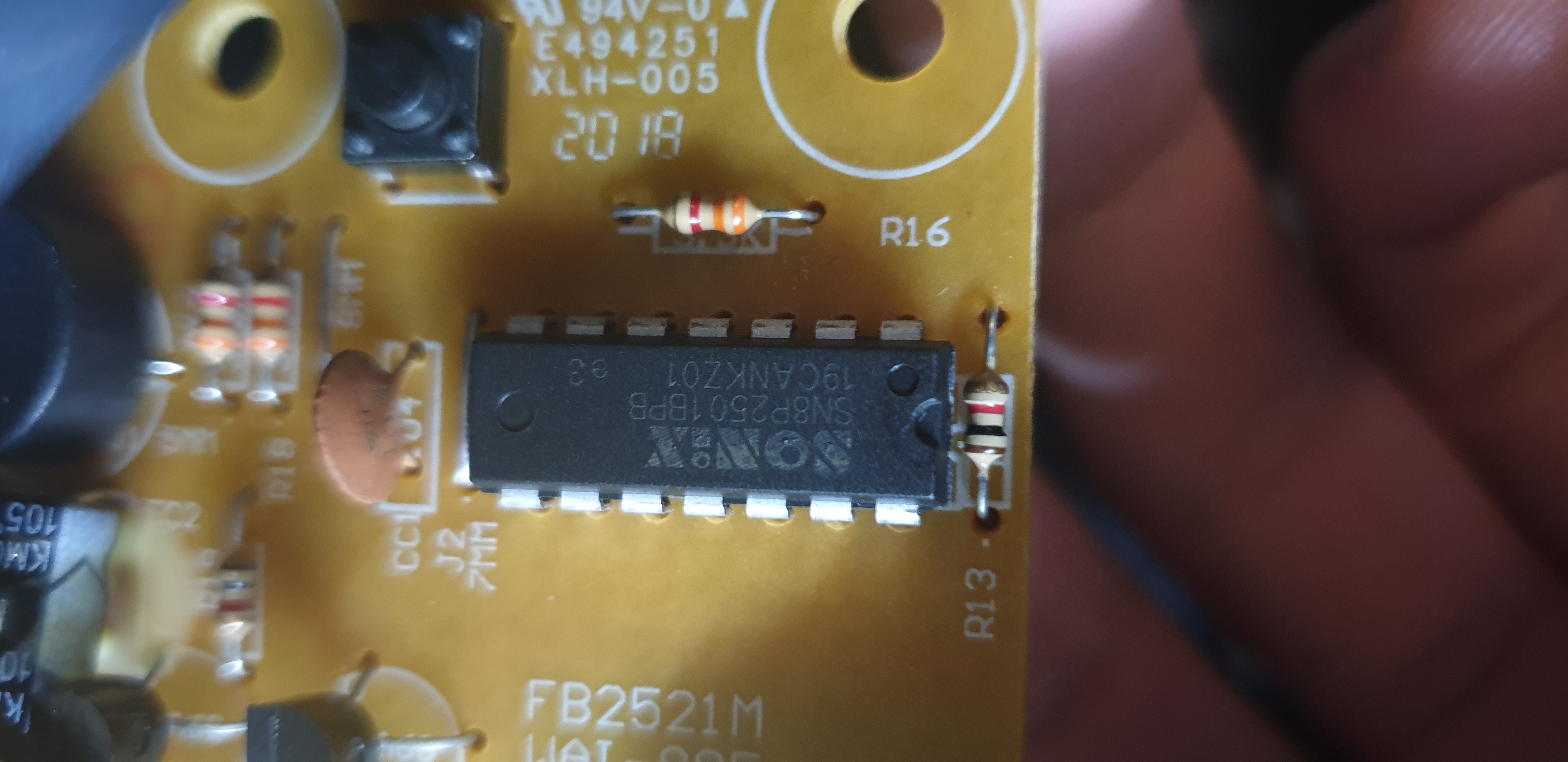
A closer look at the chip reveals that it is a Sonix SN8P2501BPB - an 8-bit micro-controller.
Pinout
With help of the Sonix IC’s datasheet I was able to create a pinout of the IC, and of how it was connected to the other components.
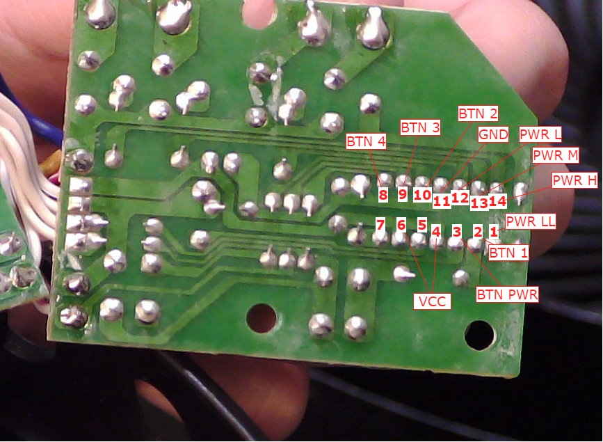
Most importantly, the pinout shows us that the push buttons corresponded to pins 2, 3, 8, 9 and 10.
It should also be noted that pressing the pushbutton brings the pin to GND - aka active on LOW
The output pins (fan level) are on pins 1, 12, 13 and 14.
5V is connected to pins 4 and 6, and GND is connected to pin 11.
Not labelled in the diagram are pins 5 and 7, which are the speaker/buzzer and reset pins respectively.
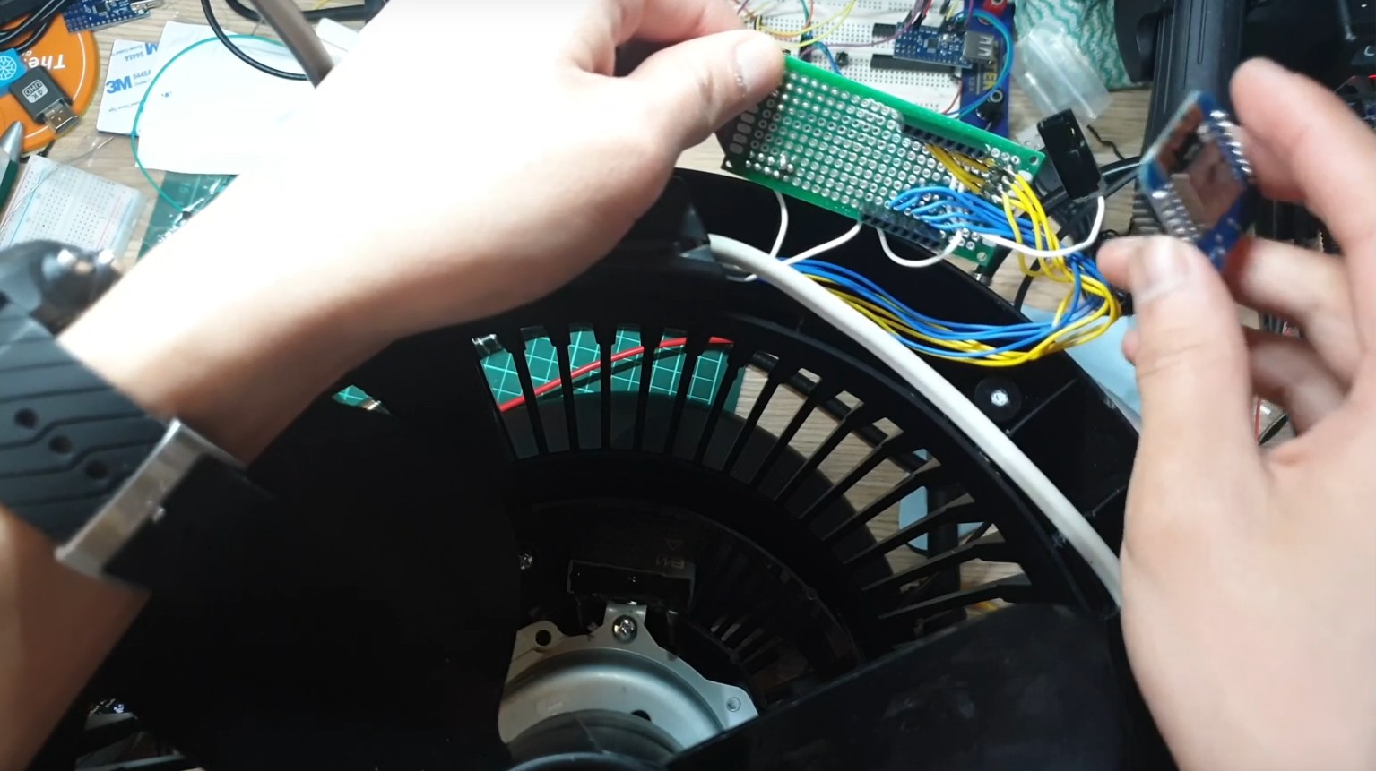
Injection
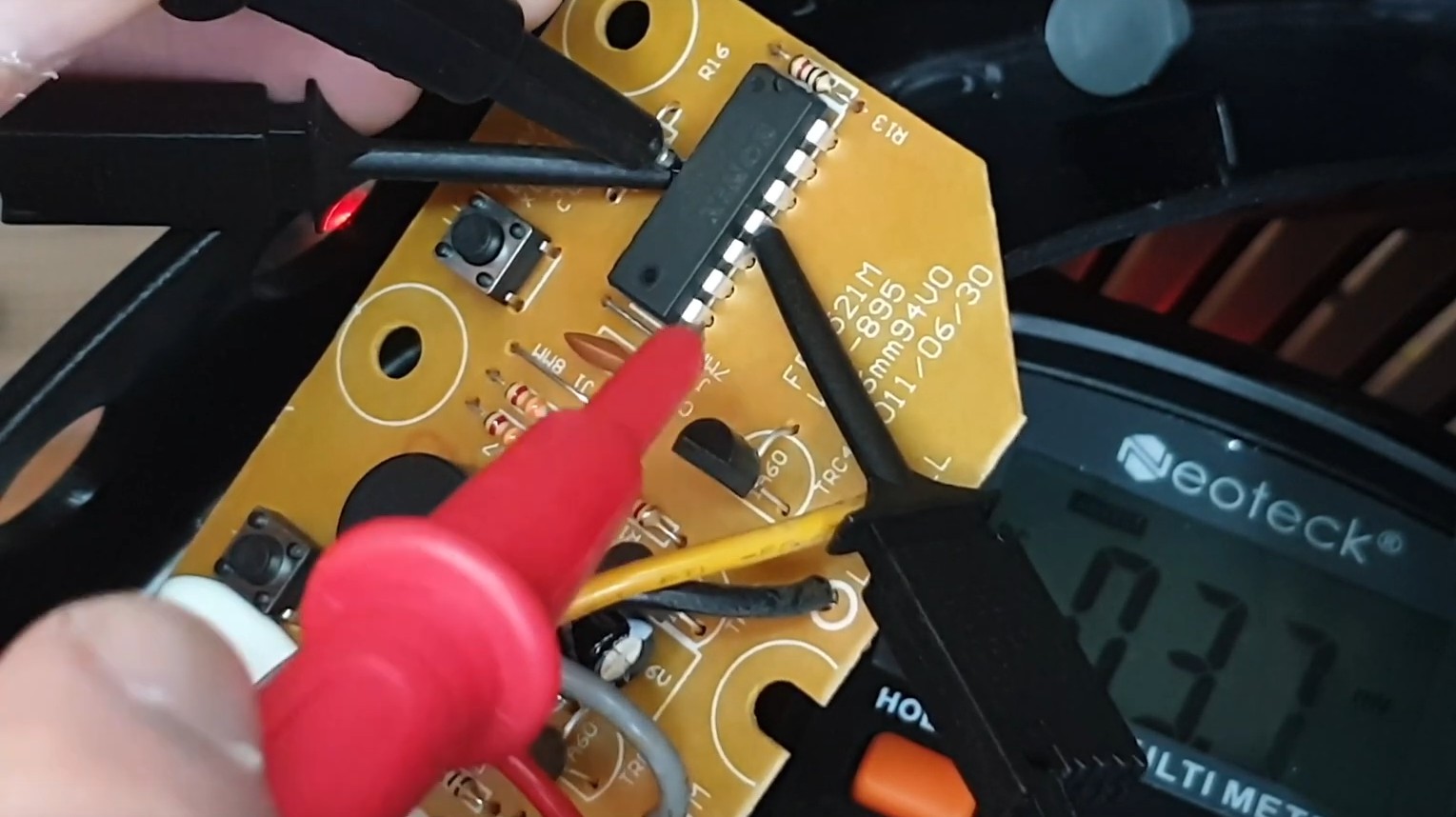
Now that I knew the pin layout of the Sonix IC, I wanted to do some manual testing of the chip to verify that an external microcontroller would work. I unplugged the AC power (scary!) and connected a 5V power supply (less scary!) to power the IC - this way the motor wouldn’t randomly turn on whilst probing the pins.
My 5V power supply died, so I just powered it off the 5V rails of a spare Arduino that was lying around
The Microcontroller
FINALLY, it’s time to whip out a microcontroller.
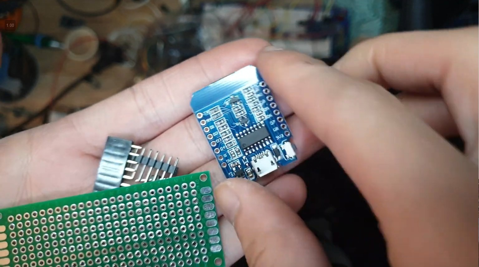
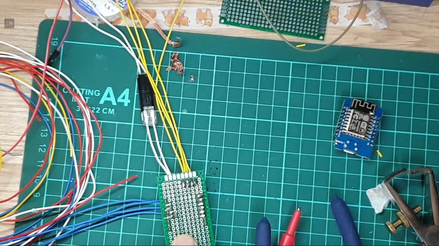
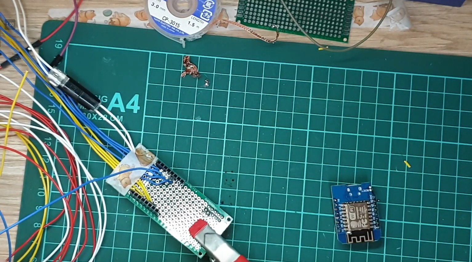
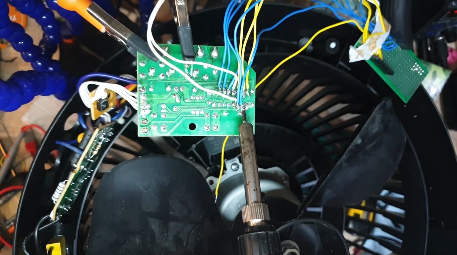
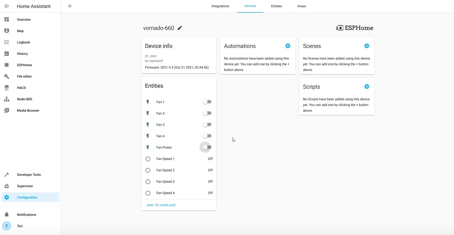
The plan was to use an ESP8266 D1 Mini board as I had bulk bought a bunch of them a while ago. The D1 Mini board had (just) enough pins to connect the 9 I/O cables (5 button triggers, 4 sense inputs) to the Sonix IC.
The pinout would be something like
- D0 - Power Button
- D5 - Level 1 Button
- D6 - Level 2 Button
- D7 - Level 3 Button
- TX - Level 4 Button
- D1 - Level 1 Sense
- D2 - Level 2 Sense
- D3 - Level 3 Sense
- D4 - Level 4 Sense
The sense pins would be used to deduce the current state of the device, since we don’t have direct access to the Sonix controller state
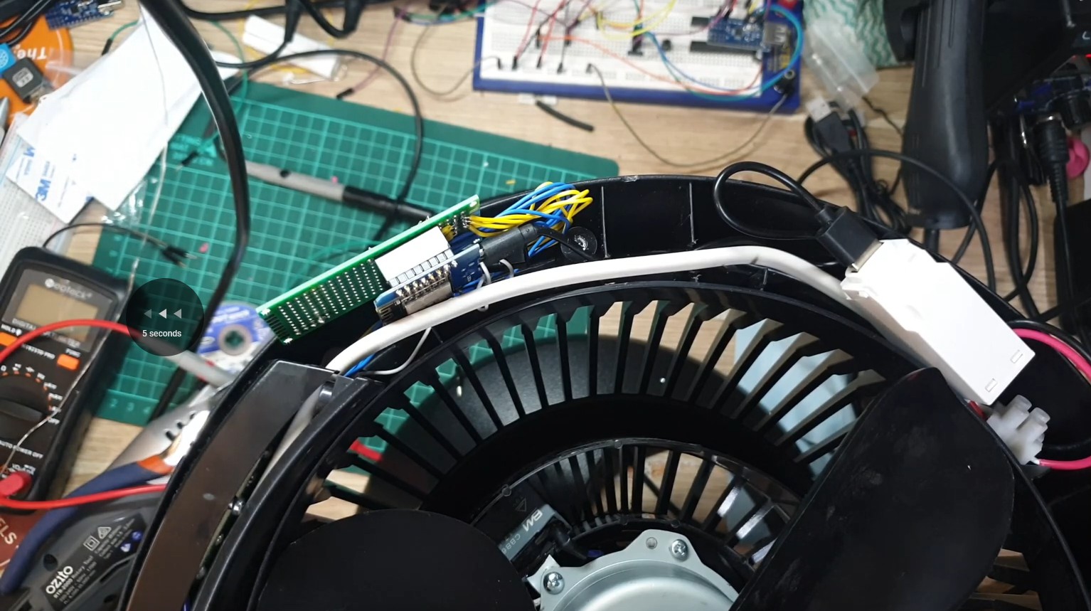
To make maintaining the ESP8266 easier; I opted to add a veroboard perfboard* and some header pins - so that I could disconnect the ESP8266 from the system if needed.
*: Should have bought veroboards… perfboards are a mistake
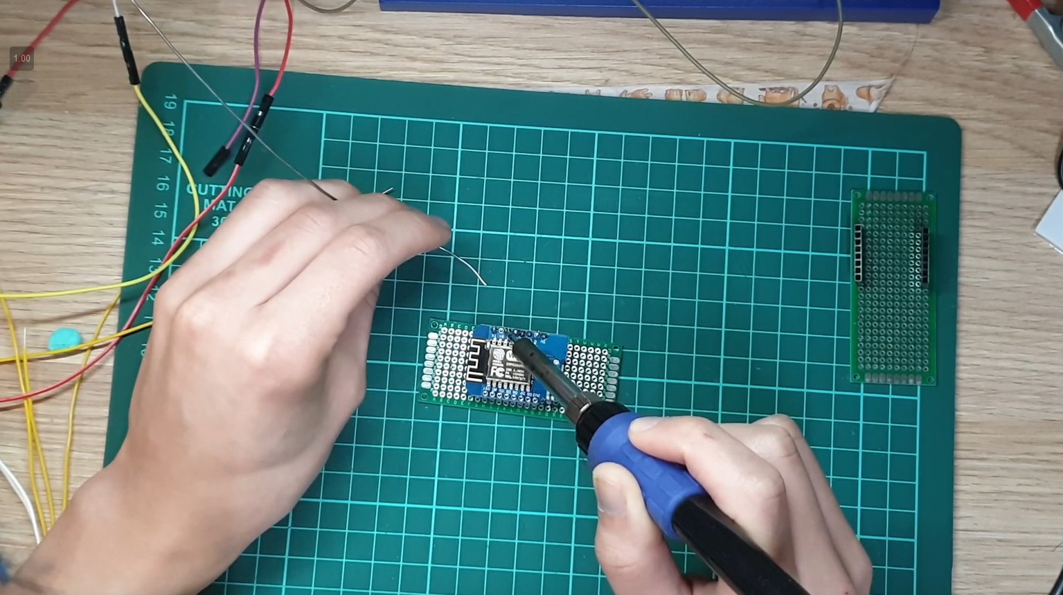
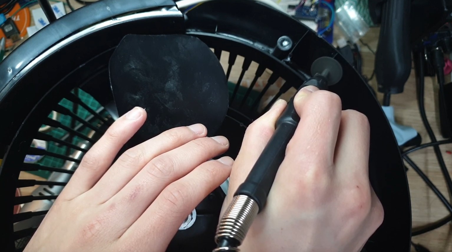
Soldering
Hehe the new soldering tip was good … until it burnt out…?
COMMENCE SOLDERING MONTAGE
END MONTAGE
You probably had enough of my questionable soldering skills, but hey feel free to criticise me even more in the recording.
Programming
GitHub: featherbear/vornado-660-esphome-esp8266
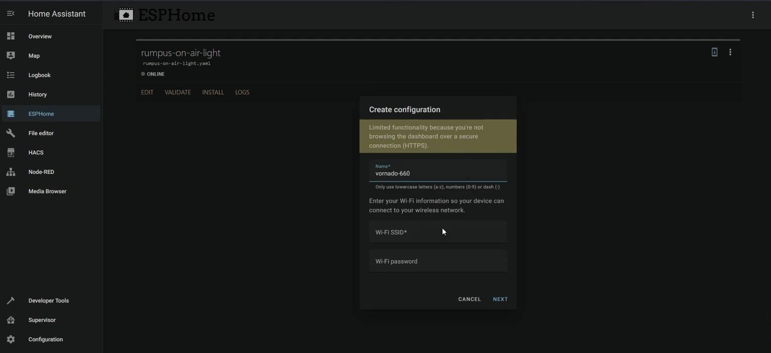
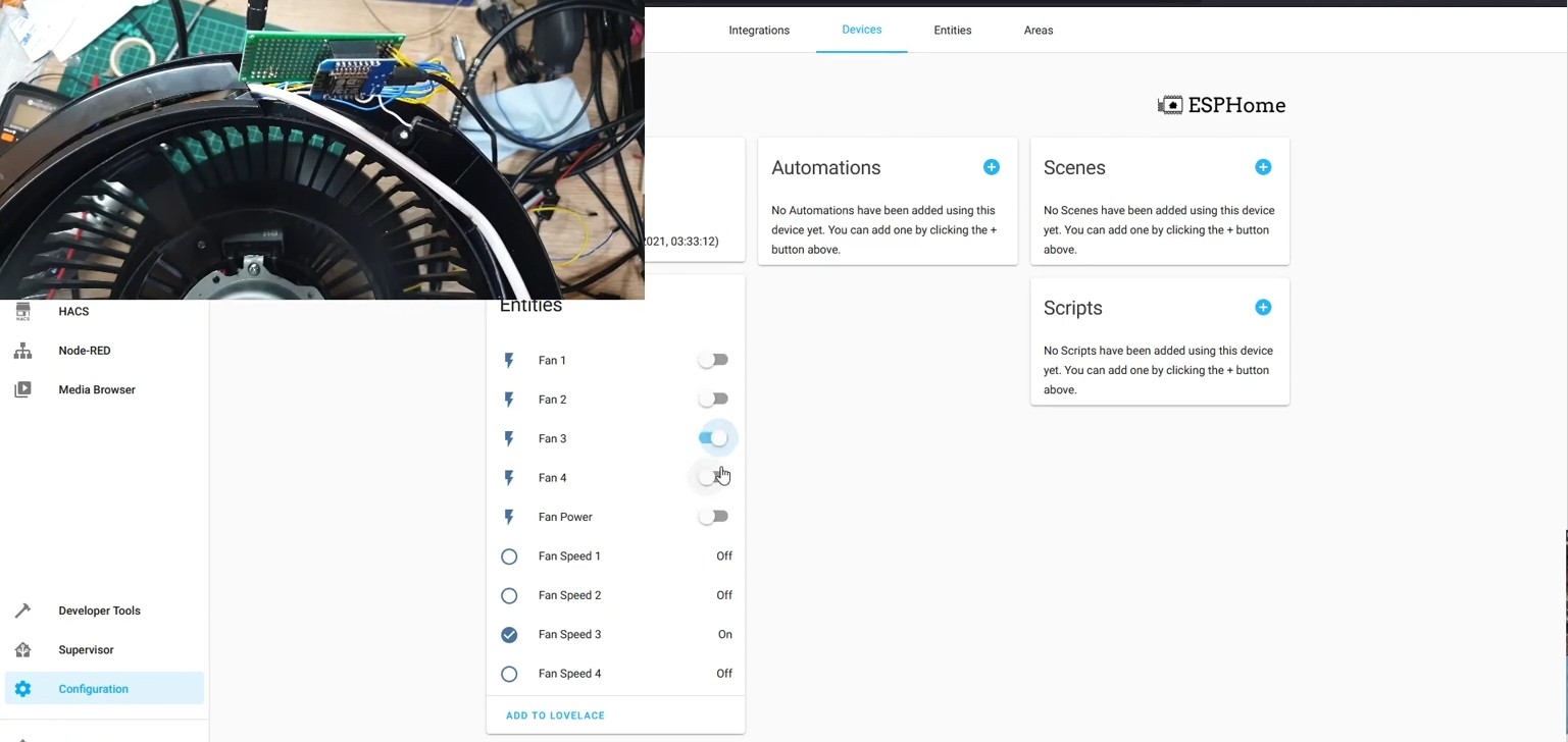
In terms of code, I flashed over ESPHome to easier integrate it within my HomeAssistant setup.
EDIT: That said, I do still need to write some code, as the basic building blocks offered in ESPHome aren’t advanced enough to nicely implement my intended functionality.
As I was using the ESPHome framework, I could define the pin behaviours in the YAML config file (partial YAML available here). After some messing around with different pin types and values were we able to get everything working!
WHY. DON’T. YOU. CLOSE.
The design of the frame allowed me to shove the ESP8266 board (and power supply) in a gap along the edges, but the lid closed into those gaps; so I cut out bits of the plastic with a dremel.
With enough cut out, and with a little bit of force I was able to close up the unit and replace the screws!
Bugs and The Overlooked
Boot Assertion of Pin D8
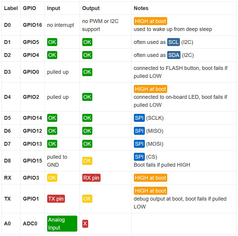
According to this diagram from randomnerdtutorials.com, pin D8 must be LOW when the ESP8266 chip is booting, else it will fail to boot.
My original design (and hence solder paths) had the Level 4 Button assigned to D8 - however due to the original circuit’s “active on LOW” nature, D8 was asserted to HIGH which caused the ESP8266 to not boot when connected to the device.
I had to change the Level 4 Button (and solder path) to use the TX pin
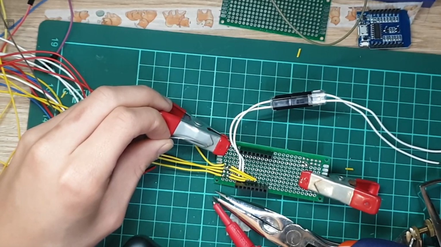
Power
As noted from the author of the fireplace blower project, their microcontroller did not power on when connected to the internal 5V supply of the Vornado - likely due to power limitations.
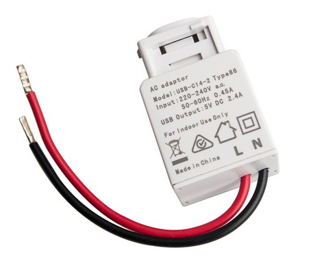
I had a DETA branded 240VAC to 5VDC @ 2.4A USB keystone (similar to but not pictured above) so I decided to use that instead to power the device
Wrap-up
GitHub: featherbear/vornado-660-esphome-esp8266
Sooo.. after 12 hours of doing this (over four sessions) we have a WiFi-enabled Vornado 660!
I do have to admit that currently the physical buttons don’t work, due to the ‘wet’ output of the ESP8266 pins (where each output pin is supplying 5V when inactive). To make this work seamlessly with the physical buttons, I will need to write some custom code to change the pin mode of the output pins; but I’ll save that for a later day.
Otherwise, success!
YouTube
If you want to see me suffer for twelve hours / suffer watching me for twelve hours, you can have a look at the entire project recording here: https://www.youtube.com/playlist?list=PLD7TGWg7V1ZYyiaRLavlBz-ZqkRNBZQFs
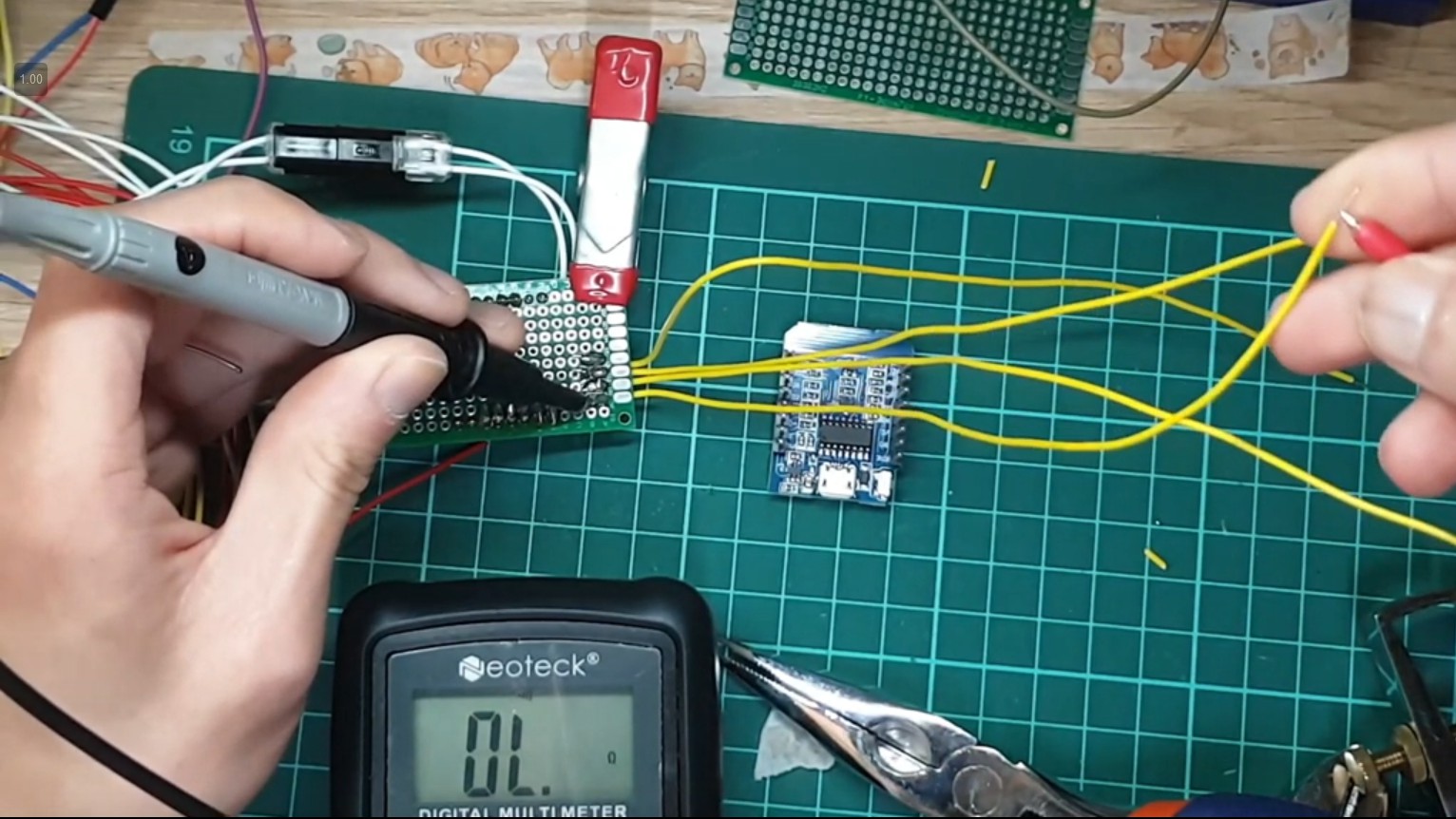
Aside - Power Consumption
The ESP8266 draws around 0.6W of energy.
Power Draw (excluding ESP8266 usage)
- Level 1 - 40.8W
- Level 2 - 43.3W
- Level 3 - 45.2W
- Level 4 - 54.7W
Level 4 draws quite a bit more power than level 3 - So I would recommend to just stay on level 3; unless you’re trying to move a lot of heat away